CHAPTER 30
THE CONDITION OF THE VISOR
This big steel construction
- actually having been the bow of the ESTONIA - was standing ashore in Hangö
in upside down condition and in the open air completely unprotected from November
1994 to November 1999.
It has been
carefully examined, measured and photographed. Several steel parts were cut
off and metalurgically examined by Prof. Dr. Hoffmeister from the University
of the Armed Forces, Hamburg and the results are outlined in Subchapter 34.4.
A selection of the relevant photographs has been arranged on sheets in accordance with the following areas of interest:
1 = Outer hull
2 = Ramp house
S 3 = Starboard visor arm
P 3 = Port visor arm
S 4 = Starboard actuator (visor lifting cylinder)
P 4 = Port actuator (visor lifting cylinder)
S 5 = Starboard aft bulkhead
P 5 = Port aft bulkhead
6 = Visor bottom
S 7 = Starboard inner longitudinal bulkhead
P 7 = Port inner longitudinal bulkhead
8 = Internal structure
9 = The 3rd stringer
All
sheets are arranged on a "General View".
(click for full
page images)
Each item is explained
by means of the numbered detail photos arranged on one or more sheets around
an overview drawing and detail drawings showing the particular area with explanations.
These sheets can be found at the beginning of the explanations and it is recommendable
to look at them when reading the comments. In the following all pictures shall
be explained and evaluated. Whenever considered appropriate additional pictures
and/or drawings are added and explained as well.
The original
design and construction of the visor is explained in Subchapter 2.6.2 and
of the actuating, monitoring and control system in Subchapter 2.6.6.
(click for full
page images)
In detail:
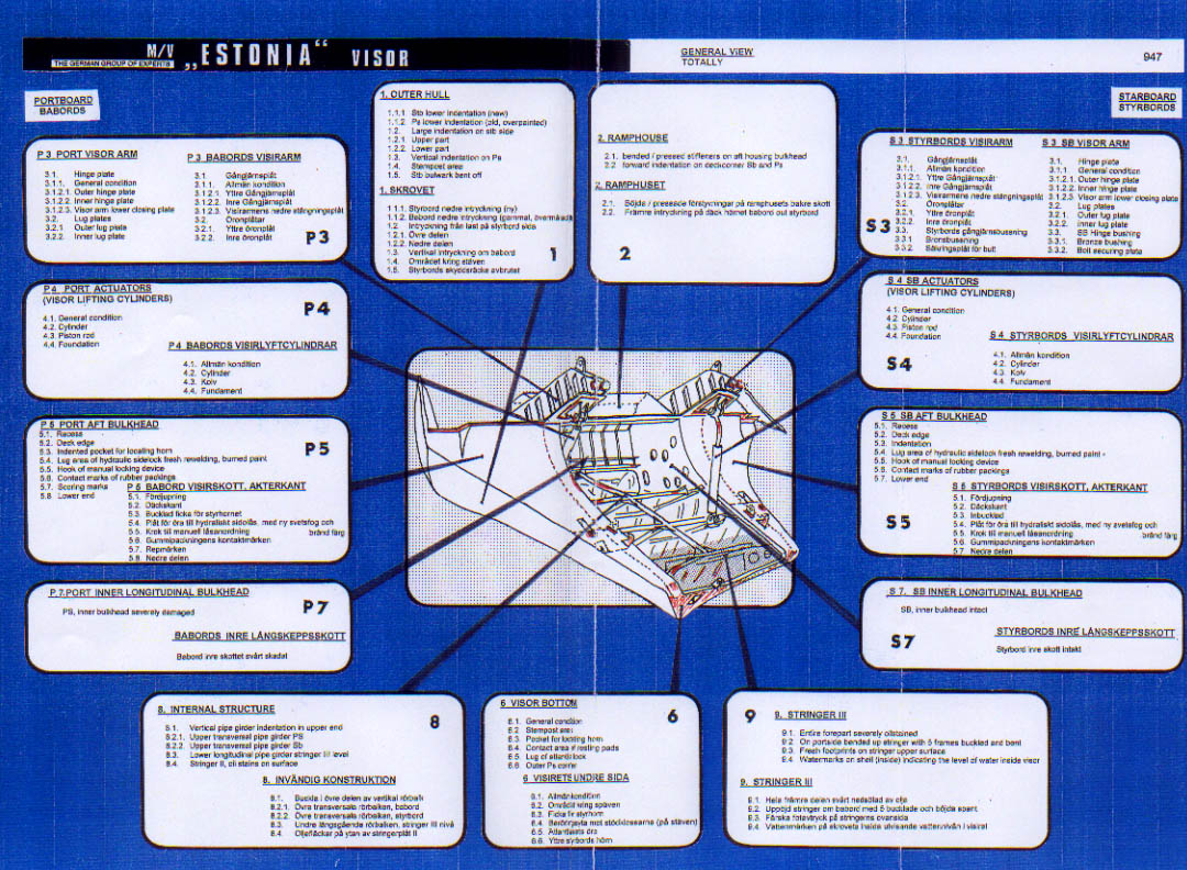
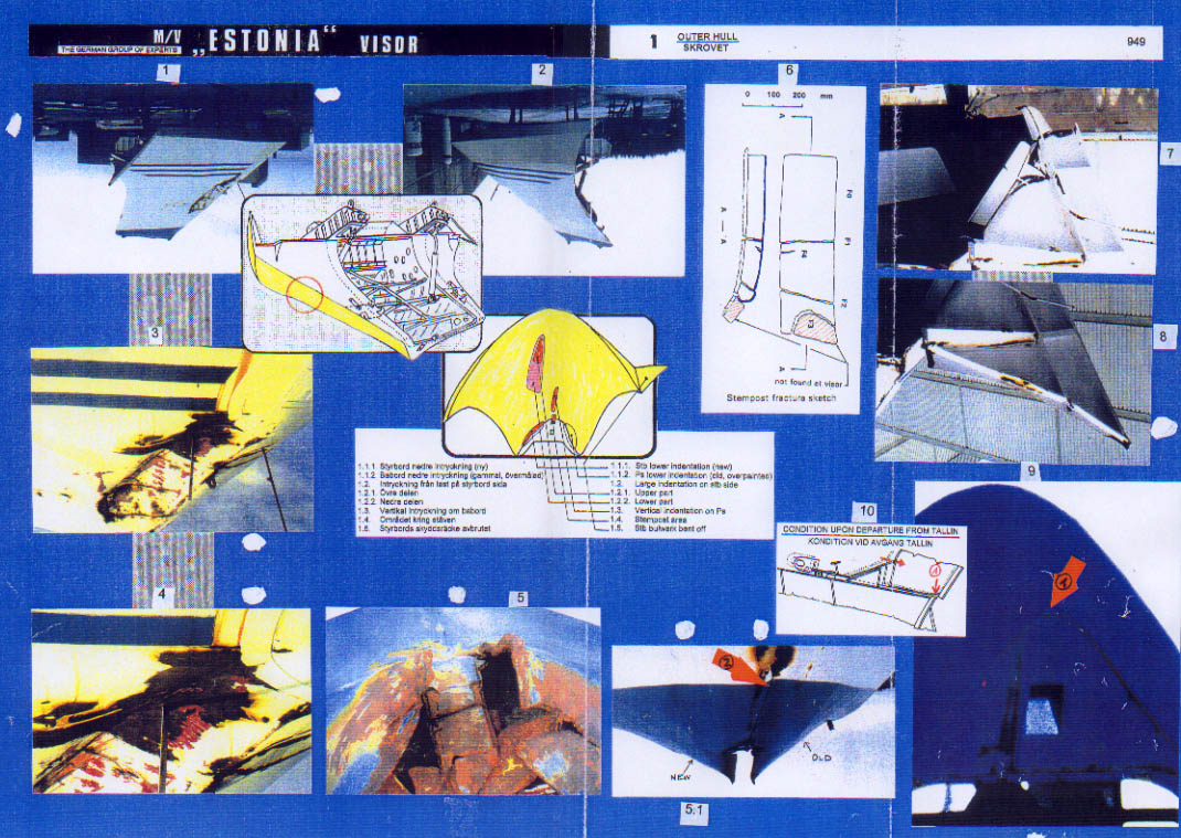
1 - Outer Hull pictures:
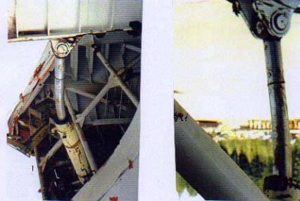
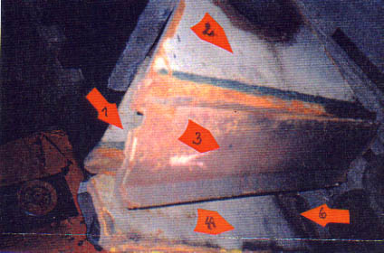
1 and 2 - show the visor ashore at Hangö in the position as it had been attached to the ship.
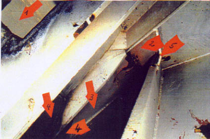
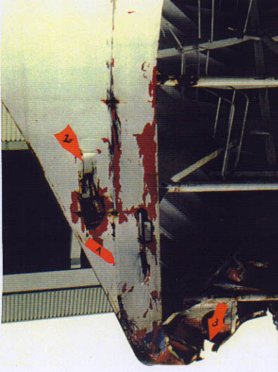
3 - shows the large indentation at starboard side of which the larger, lower part was probably caused by contact with the bulbous bow. This larger indentation extends down to the gap at the stempost. There was already a rather deep vertical indentation from a previous occurrence.
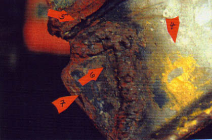
4 - shows the upper part of the large indentation which looks completely different, although the indentation from below extends into this severely corroded and apparently previously indented area without any coating whatsoever.
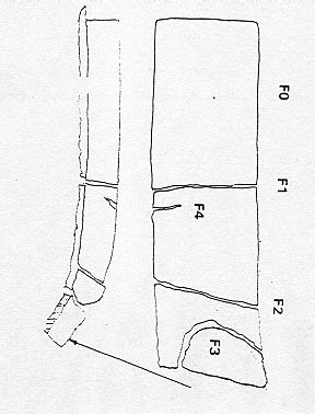
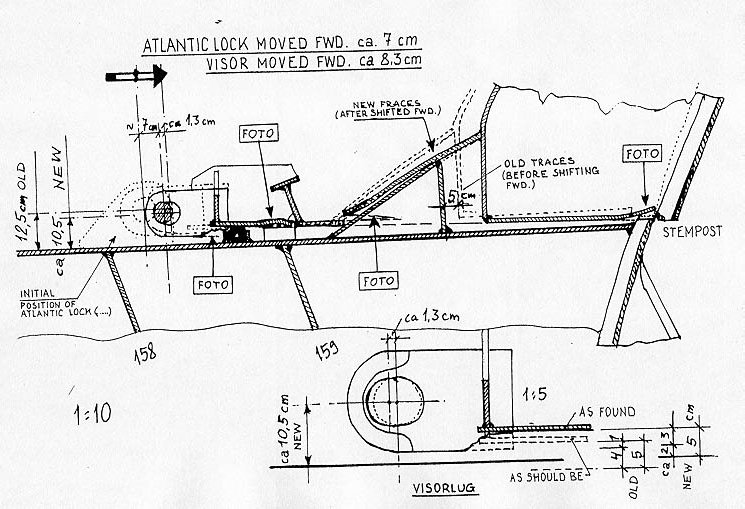
5 - shows the collapsed stempost area. The stempost was found to have cracked four times - see drawing 6 - apparently by fatigue, of which the lower crack penetrated completely some time before the casualty and the lower part, F 3 on the drawing, had disappeared leaving a gap in the stempost respectively a hole in the bottom of the visor. The drawing No. 6 also shows that the INERTA ice paint - last applied in January 1994 - had penetrated the cracks F 1, F 3 and F 4 up to 50% of the thickness of the stempost. This means that the stempost had been cracked through up to 50% already in January 1994. See also Subchapters 12.5 and 34.4.
5.1 - shows the lower forward part of the visor with the deep vertical indentation (arrow 2) of old origin, the gap in the stempost area caused by the ice knife on top of the bulbous bow, the small indentation at the starboard side (new) which is apparently casualty related and the large deep indentation at port side (old) which is of old origin and was probably caused by contact with ice.
7 and 8 - show the bent-off starboard aft part of the bulwark. This damage occurred probably when the visor was hammering on the bow ramp and the ferry was severely heeled to starboard.
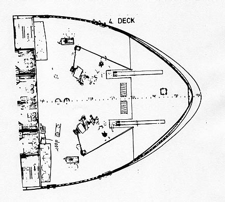
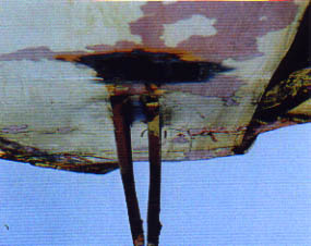
9 and 10 - with drawing (10) incorporated show the visor bottom and arrow 1 points to the indented stempost/bottom plating. The reason for this indentation was the misaligned visor as indicated on the drawing, i.e. the forepart of the visor overlapped the forepart of the forepeak deck to such an extent that the stempost of the visor was no more resting on the stempost of the forecastle deck, but that the stempost part of the forepeak deck was in contact with the bottom plating of the visor which was neither designed nor dimensioned to carry the weight of the visor. Therefore the bottom became firstly indented and subsequently holed.
Evaluation:
(1) There were 2 very heavy damages in the visor which were of old origin and which had led to a change of alignment and geometry of the visor when they occurred which increased during the subsequent time and which has contributed to the casualty.
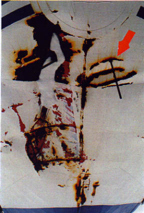
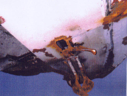
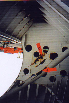
(2) The large damage to the starboard shell plating was apparently sustained in two stages, viz. at first the corroded upper part occurred and subsequently the larger lower part, which extends into the upper part, occurred. Since it is already rather unlikely that the upper part of the damage did occur during the final stage of the casualty sequence-of-events by contact with the bulbous bow, it can be excluded that the 3 sharp and deep transverse indentations to the port side of the centre line were caused by contact with any part of the bulbous bow because there is no corresponding counter-piece. The picture below shows all the indentations in the forepart of the visor. The arrow indicates the 3 horizontal indentations of which the upper and lower ones are rather deep. It has thus to be assumed that the visor had been in contact with some other object either before the casualty scenario began or after it had ended, possibly during the attempts to raise the visor.
(3) At least 2 fatigue cracks had penetrated the stempost already by about 50% when ice paint was applied the last time which was between 10 and 14 January 1994 in the shipyard at Naantali. During the following nine months up to the casualty the cracks had to propagate further and the lowest one did fully penetrate the stempost which led to the breaking away of part F 3 (see drawing below) and the creation of a corresponding hole in the visor bottom and, consequently, the faster flooding of the visor inside at sea.
(4) The visor was misaligned to such an extent that its forepart was overlapping the stempost of the forepeak deck - see drawing behind this page and picture 9 on sheet 1 - which had serious consequences for all the relevant parts of the visor such as locking devices, hinges, rubber packings and, last but not least, the weather tightness of the visor. Nothing fitted anymore.
(5) The drawing behind this page summarizes the findings and indicates the condition of the forepeak deck and the lower part of the visor including the lug of the Atlantic lock before departure for the last voyage.
The below drawing shows the fatigue cracked stempost from the side and from forward.
2 - Ramp House
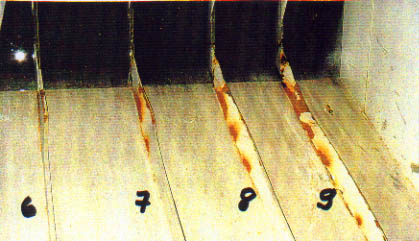
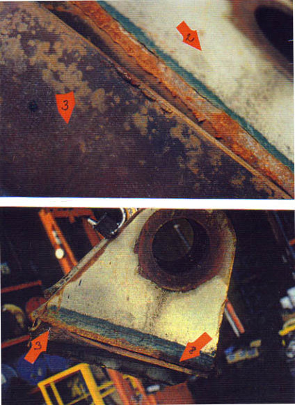
There is no sheet available for this part of the visor. The pictures show the inside of the aft part of the ramp house with 9 vertical webs each at its forward- and aft-parts. The webs are of the hp profile-type and measure 160 x 7 mm. The 4 webs at the port side of the aft part - numbered 6 to 9 - were indented to varying extent as can be seen on the picture below. Web 6 was evidently just slightly touched while web 9 was pushed flat.
The report of the Finnish expert to this 'Group of Experts', Captain Peter Jansson, about the subject matter reads as follows:
»Undamaged webs are abt. 155 mm high. There are 9 pcs webs in all Webs # 1 to 4 from the sb side are essentially undamaged, but the paint has been scraped off all of them in a line abt 20 mm down from the ramphouse upper horizontal surface plate (top).
Web # 5 is already very slightly deflected towards port and measures at 150 mm (against 155, see above). Web # 6 is deflected so that 140 mm remains, # 7 has 100 mm, # 8 has 60 mm and # 9 has 20 mm standing, while the rest of that web has been deflected to port. The depth of damage (deflection) is thus quite linear between webs 6 and 9. However the point of max damaged paint at # 1 to max deflection at # 9 seems to follow a gentle curve dropping downwards as you look to port. The ramphouse after plate with the damaged webs below.«
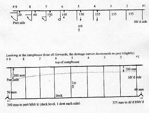
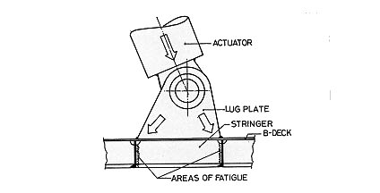
The damage configuration revealed by the above measurements indicates that the visor must have been misaligned by 4°-5° in forward/aft direction if the indenta-tions should have occurred by contact with the bow ramp, i.e. the port side of the visor had to be about 300 mm further forward than the starboard side. In other words, the port side of the visor must have moved forward while the starboard side was held back. Before such forward movement of the visor is possible at all and contact between the aft part of the visor's ramp house and the upper part of the bow ramp is possible, several initially built in obstacles have to be overcome as demonstrated by the drawing on the following page.
These are:
(a) the visor hinges have to break and the visor has to move forward;
(b) the lugs for the actuators underneath the visor arms have to cut 120 mm through 8 mm forecastle deck plating until they will strike against the strong transverse deck beam at frame 159;
(c) the lugs will have to cut through this transverse deck beam at frame 159, which is only possible after several forward/aft movements of the visor;
Note: The forces necessary for the lugs to cut through this frame have been calculated by the Technical University Hamburg-Harburg to have been about 200 ts. This means a point load of ca. 100 ts at the port side and a point load of ca. 100 ts at the starboard side. See Subchapter 34.12.
(d) the visor has to move 360 mm forward before the aft webs of the ramp house (160 x 7 mm) can come in contact with the upper part of the bow ramp;
(e) the (empty) visor weighing 55 ts, of which the main part is still absorbed by the forepeak deck, will then lean on the properly closed and locked bow ramp;
(f) as the break-load of the 2 ramp hooks was 42 ts each, i.e. 84 ts, and the break-load of the 4 securing bolts was 25 ts each, i.e. in total the break-load of the bow ramp's locking devices was 184 ts, the visor will lean against the ramp and nothing will happen as it is proven by the MARIELLA incident described in Chapter 33.
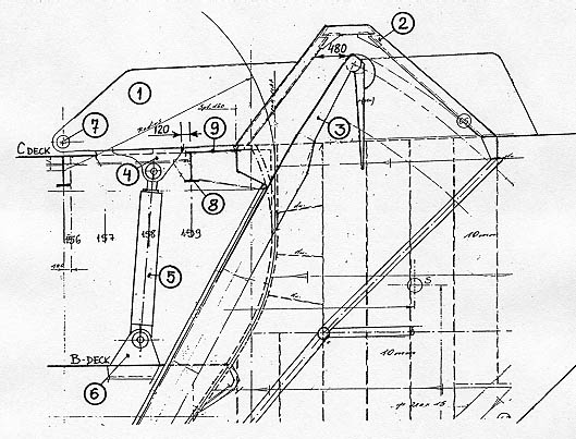
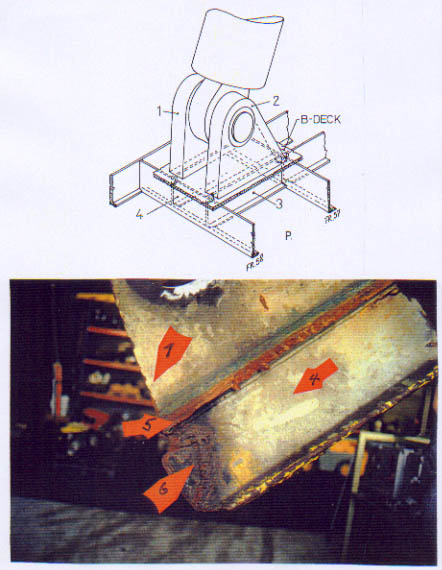
1 - Visor arm
2 - Ramp house
3 - Bow ramp
4 - Lug underneath visorarm
5 - Actuator
6 - Actuator foundation on B - deck
7 - Visor Hinges
8 - Frame 159 =400x9mm
deck beam = 160x22mm
9 - Forecastle deck (C -deck) = 8mm
This, however, was not the ESTONIA scenario because some of the initially built in obstacles were no more in existence, viz.
(g) the visor was no more watertight but water-filled to the outside level which increased its weight to about 200 ts, and
(h) the bow ramp was most probably not secured at all - see Subchapter 29.2 and
(j) visor hinges and locking devices were considerably damaged/worn and their load-carrying capacity was reduced to a fraction of its original value.
Therefore, and due
to other circumstances, a casualty scenario as described in Chapter 31 was
able to develop which led to the sinking of the ESTONIA and which requires
a detailed examination in order to find out what actually caused the indentations
to webs 6 - 9 inside the ramp house of the visor.
The damage
is most extensive at web 9 and then decreasing until web 5 which, as well
as the starboard side webs 1 - 4, are not affected at all - see picture below.
The visor must have been misaligned by ca. 4-5° in relation to the bow ramp
being connected to the vessel.
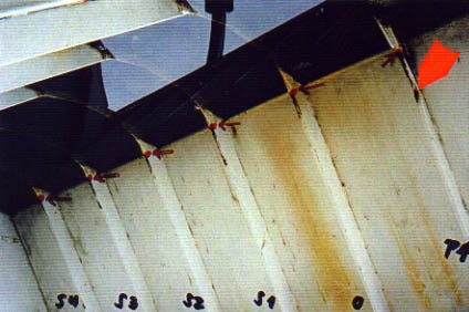
The arrow indicates the point of contact on web 9. The next frame 5, which is the centre line, and the following frames to starboard have no marks at this level.
This means that
when web 9 came in contact with the port side of the bow ramp and was pressed
together from 160 mm to 20 mm the corresponding web 1 at the starboard side
of the ramp house was 360 ./. 160 = 200 mm away from the starboard side of
the bow ramp. Due to the narrow construction, such a misalignment of the visor
is not possible as long as the visor lugs move within the forecastle deck
area aft of the deck-beam at frame 159 and as long as both actuators are connected
to the B-deck. As will be shown on sheet P 4 + S 4 this was no more the case
with the foundation of the port actuator.
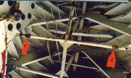
Also visible
on the two pictures above are slight scorings inside the ramp house from web
1 through web 9 which could indicate a slight contact at another time, earlier
or later (see red arrows on both pictures). The scoring marks are just below
the brackets between vertical/horizontal webs which would be the areas of
contact when visor and bow ramp are in normal condition as on the drawings.
Since the points
of deepest indentation on webs 6 through 9 are, however, located about 300
mm deeper, this indicates that the visor was at its normal height at the time
of this contact, but raised by about this distance in relation to the upper
part of the bow ramp.
There is, however,
the much more realistic possibility that the port side of the bow ramp came
in contact with this particular area inside the ramp house when the visor
was hanging on the ramp at a rather late stage of the casualty scenario. Then
the vessel was on the side and the visor was close to sliding off the ramp
due to the vessel heeling some 120°/130°. This will be explained in Chapter
31 - The Casualty Scenario.
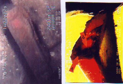
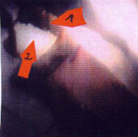
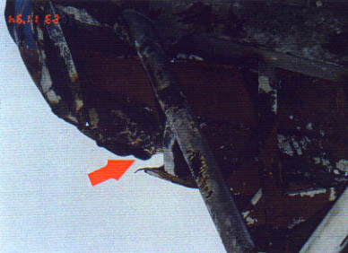
Although the upper transverse crossbar inside the visor shows respective damage - see arrow 1 on the picture below - the corresponding part at the port outer longitudinal girder of the bow ramp does not. This is confirmed by the image further down,
taken from the ROV video made on 09.10.94 which shows the port outer girder underside of the bow ramp in way of the contact area with the above-mentioned crossbar. There is no damage, the paint is completely unaffected (the diago-nally running stripe being a wire).
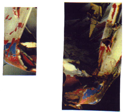
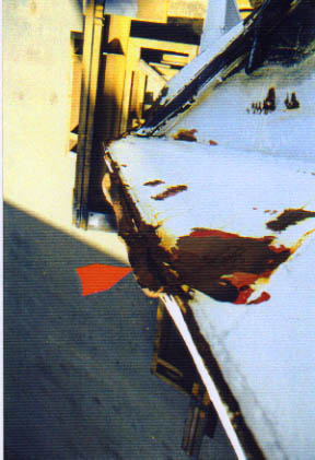
It is obvious that this quite heavy damage shown on the picture on page 961 was caused by impact - see close-up below - and that this impact did not happen too long ago because the cracked paint is still hanging loose. It cannot have been caused by the ramp, at least not at an early stage as explained before. The damage must have been caused when the visor was labouring on the ramp for more than 30 minutes until the heel of the vessel was sufficiently big to let the visor slide off the ramp. During this time, this and other damage to the
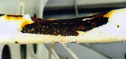
port side of the visor was created by heavy contact with the ramp.
The scoring marks - arrow 1 on the photo on page 961 - at the starboard side of the same crossbeam in way of the first stringer level are not casualty related because except for the middle one the respective areas cannot be reached by the bow ramp. It has to be assumed that these scorings were caused by other means before the casualty.
The indentations/scorings at the vertical beam are discussed in item 8 - Internal Structure.
In summary of the before mentioned the following has been established:
(1) There may have been a previous however light contact between visor and bow ramp when both were in normal condition to each other. Such contact could not be explained by this 'Group of Experts', because contact between ramp and ramp house under normal conditions is only possible if the visor hinges are broken or disconnected.
(2) There has however been a stronger contact between the port side of the bow ramp and the port webs of the ramp house only when the visor was misaligned in relation to the bow ramp by ca. 4°, i.e. the port side of the visor was about 300 mm more forward than the starboard side, a condition which was only possible after the hinges had failed and the lugs under-neath the visor arms had broken through the deck beam at frame 159.
(3) This is supported by the apparent fact that the bow ramp was not locked and the visor was water-filled to the outboard level and was weighing about 200 ts, instead of 55 ts in empty condition.
(4) The bow ramp did not crash into the visor onto the cross-beam at 1st stringer level and did not cause the respective damage on port side because neither the corresponding part of the bow ramp nor the corresponding part of the starboard side of the same cross-beam do show any damage of similar nature.
(5) Consequently the bow ramp was not pulled open when the contact occurred which caused the indentations/scorings to the four port webs in the aft part of the ramp house.
(6) It has however to be assumed that this contact occurred in the final stage when the visor separated from the vessel and the bow ramp was kicked up by the port aft bottom part of the visor as it will be explained in Chapter 31 - The Casualty Scenario.
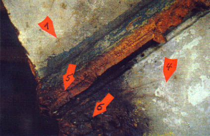
Finally attention has to be drawn to one indentation pushed at each side into the forward deck beam of the visor, i.e. the lower side of the forward part of the ramp house as indicated on the two pictures on the next page. According to drawing on page 956 the port indentation is 240 mm away from the inner bulkhead and the starboard one 325 m. This means that these indentations were most probably caused by the bell cranks being the most upwards extending parts of the bow ramp. This must have occurred at a time when the visor was hanging on the bow ramp already, i.e. the contact area having been the part inner bulkhead. Therefore the distance between bow ramp and port inner bulkhead has as small as possible - 240 mm - while the opposite distance between the bow ramp and the starboard inner bulkhead was as big as possible - 325 mm. This is also the explanation for the apparent fact that the port inner bulkhead was very severely distorted and partly cracked while the starboard inner bulkhead remained completely unaffected even without paint scratches. See also S 4 and P4 - The Inner Bulkheads - further down.
(click for full
page images)
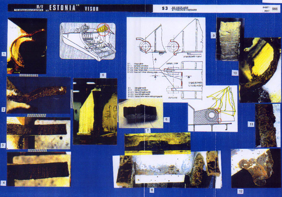
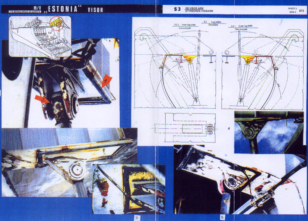
S 3 - Starboard Visor Arm - Sheet 1 The sheet shows the overview drawing indicating the area in question, 4 detail drawings demonstrating the damage to the broken hinge plates at the aft end of the visor arm and in total 15 photos which underline this disastrous condition of the starboard hinge arrangement.
In detail:
Pictures:
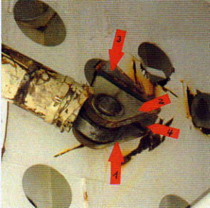
1 - shows the remains of the starboard hinge plates still attached to the visor (they were cut off upon the instructions of the JAIC in January 1995 and were transported to the Royal Technical Institute (KTH) in Stockholm for examination). The very bad condition, especially of the outer hinge plate is obvious. The deep burning marks and the missing metal are striking. All this is confirmed by the video film made by a passenger on 17.09.94 from the open forepart of deck 8 - see also Subchapter 12.5 - i.e. 10 days before the catastrophe. The image below shows a sequence of this video.
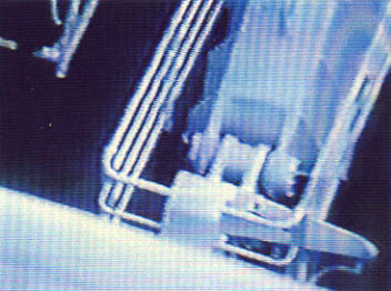
It demonstrates that,
- the whole hinge arrangement is severely misaligned;
- the outer bushing is extending too much to the outside and is twisted;
- the lower part of this bushing as well as the securing plate are missing;
- there is a big gap between the inner part of this bushing and the outer hinge plate fitted on the forecastle deck;
just to mention
the main and most obvious deficiencies. The video tape was analysed in detail
by the British Reconnaissance expert Bryan Roberts and his findings are discussed
in Subchapters 12.5 and 34.9 and his report is attached as Enclosure
12.5.180.
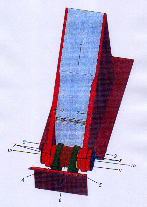
For easy reference
of the reader a drawing with explanations showing one of the visor hinges
is attached behind this page.
The numbers refer to the annotated parts on the drawing behind this page.
1 Visor Arm
2 Inner Visor Hinge Plate
3 Outer Visor Hinge Plate
4 Inner Vessel Hinge Plate
5 Outer Vessel Hinge Plate
6 Fixed Bushing
7 Inner Steel Bushing
8 Outer Steel Bushing
9 Securing Plates ( both sides )
10 Visor Arm Bolt and Bolt Axis
11 Securing Plate and 4 Bolts ( bolt sides )
12 Distance Ring ( both sides )
The drawing was taken from the report of Bryan Roberts.
The bushing, obviously having broken out of this inner hinge plate, was recovered by divers and was thus available for examination also by the metallurgical expert on behalf of this 'Group of Experts' and reference is made to the Report of Prof. Dr. Hoffmeister - see Subchapter 34.4 - Enclosure 30.417. Further, the recovered bushing is shown in detail on Sheet 3 and shall be discussed subsequently.
The explanation of
Sheet 1 continues:
Pictures:
2, 3, 4 - show the upper part of the starboard inner hinge plate with very deep burning marks. Each burning mark is a crack starter as can be seen e.g. on pictures 3 and 4 where the hinge plate could have broken as well. The burning marks and its fatal consequences for strength and load carrying capacity were among others examined and analysed by Prof. Dr. Hoffmeister of the University of the Armed Forces, Hamburg - See Subchapter 34.4.
5 - shows the starboard inner hinge plate, respectively it remains still attached to the visor.
Note: Upon instruction of the JAIC both the port and the starboard hinge plates were cut off the visor in January 1995 and transported to the Royal Technical University in Stockholm. They should now be in the possession of N&T.
6 - shows a cut through the part shown on pictures 1 - 4.
7 - shows the deep indentation in the base plate (visor arm lower closing plate) of the visor arm caused by repeated heavy contacts with the hinge parts on the forecastle deck during the visor's forward/aft movements.
8 - shows the cut-off starboard hinge remains.
9 - shows the upper end of this hinge plate which - same as the inner one - had not been exposed to hammering.
10 - shows the outer hinge plate with the broken lower part hammered flat.
11 - shows the deep burning marks at the inside of the hinge plate.
12 - shows the lower, heavily hammered part.
Note: The condition of the corresponding parts on the forecastle deck is explained in Subchapter 29.2 - Sheets S 1 / P 1.
The damage having been caused to these starboard visor hinges sometime before the casualty is well documented by the report of the reconnaissance expert Bryan Roberts - see Subchapters 12.5/34.9 and Enclosure 12.5.180. Therefore the following facts are considered to be established:
(1) The hinges were gross negligently repaired by burning out the old bushings and replacing them with new ones (see sheet 3), i.e.
- the steel bushing
- the bronze bushing
- the securing plate
(2) The repairers were obviously unable to re-install the previous condition because
- the steel bushing was inside the visor hinge plate only by about 1/3 (should be 50%) while about 2/3 were outside the hinge plate;
- the steel bushing with the bronze bushing inside was twisted anti-clockwise;
- the lower parts of the steel bushing and apparently also of the bronze bushing were cut off;
- the securing plate was missing;
- the bolt was not visible although it should have been.
(3) There were gaps of up to 25 mm between hinge plate and steel bushing.
(4) The hinge plates inside were covered by deep burning marks from which cracks had propagated the material very deeply. Thereby the load carrying capacity was reduced to 20% or less of the original strength. See also Subchapter 34.4.
(5) Due to the extent of crack propagation the hinges could practically have failed at any time in port or at sea.
(6) During the casualty scenario only the lower part of the outer hinge plate had been exposed to hammering.
(click for full
page images)
S 3 - Starboard Visor Arm - Sheet 2
The overview drawing indicates the area in question and 2 detail drawings demonstrate the forward/aft movement of the visor whereby the inner side and the outer side of the lug plates below the visor arms were deeply scored / scraped. 5 photographs show the conditions of these lug plates, which evidently had cut through the deck beam of the vessel located at frame 159.
In detail:
Pictures:
1 - shows the inner and outer lug plates underneath the visor arm by which the actuator is connected to the visor looking from forward to aft. These are the parts of the plates which did first cut through the deck plating and then through the deck beam at frame 159. The rubber packing - arrow 1 - to seal the opening in the forecastle deck for the actuator is apparently unaffected and intact. The spherical bearing be-tween the lug plates and the actuator is clearly visible - see arrow 2;
2 - shows the starboard inner lug plate with one rather deeply engraved area of scraping marks indicating arc type movements of the visor and some smaller contact marks.
3 - shows the area of the visor arm between the lug plates and the aft bulkhead of the visor with some contact marks, however, basically undamaged paint which is also visible on the following picture 4, although - according to the JAIC - this part of the visor arm had been resting on the forecastle deck thereby creating the leverage effect which allegedly broke the hinges. This was obviously not the case.
4 / 5 - show the starboard outer lug plate with more and deeper scraping marks indicating the way the visor had moved as long as the lugs were inside the forecastle deck. Contrary to the arc type marks on the inner lug plate these marks are deeper and straight indicating longer and more heavy contact.
The following facts are considered to be established:
(1) The intact rubber packing underneath the visor arm indicates that this side of the visor had been slightly raised during the time when the visor was moving forward/aft in the process of cutting through the deck beam at frame 159 (contrary to the port side).
(2) The deep scorings at both the outer and the inner lug plates indicate that the starboard hinge broke earlier, i.e. when the vessel either - was only slightly heeling to starboard as it had been the case for the last hour, or - was already rolling to both sides - though more to starboard than to port - about 1 or 2 minutes before the big heel to starboard.
(3) The scorings at the outer plate are, however, deeper and more extensive indicating that there has been heavier and longer contact between this plate and the steel parts cut through which was most probably caused by the increasing heel to starboard.
(click for full
page images)
S 3 = Starboard
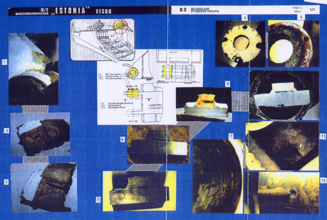
Visor Arm - Sheet 3
The overview
drawing indicates the area in question and 3 detail drawings demonstrate the
original location of the recovered bushing. 12 photographs show the condition
of this bushing and its components.
In detail:
Pictures:
1 - shows the recovered bushing fitted into the starboard inner visor hinge remains. Since this is the only one of the 4 hinge remains into which the bushing fits in respect of roughness of the surfaces and broken parts of welding seams, it has to be assumed that the bushing recovered originates from the starboard inner hinge plate of the visor.
2, 3, 6 - show part of this bushing with part of the fractured visor hinge plate still attached to it. This part is shown in more detail after the hinge-plate part had been cut off on the following page (pictures a - c). The pictures reveal the following:
- The welding seams between bushing and hinge plate are of poor quality and only 7-8 mm thick whereas the originals were about 15 mm thick.
- The same welding seams apparently cracked frequently and it had been attempted to close the cracks by welding which resulted in welding material penetrating through the cracks into the gap between the hinge plate and bushing. See arrows 1 on pictures a and c.
- The surface of the bushing in way of the hinge plate shows corrosion which indicates that the space between bushing/hinge plate, which should be sealed airtight by the welding seams, had not been airtight anymore for some time already obviously due to the crack propagation in the too thin welding seams and/or due to unprofessional welding.
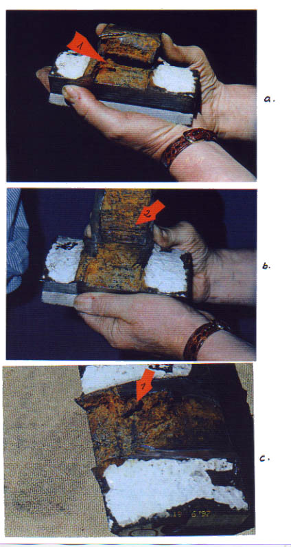
- The inside of the hinge plates were damaged by deep burning marks (see arrow 2 on picture b) from which crack propagation into the material of the hinge plates started and after the cracks had penetrated 50-60% of the material the remaining part of the hinge plate failed in the sheer mode.
- The surface of the bushing, corresponding to the inside of the hinge plate with the burning marks explained above, does not show burning marks, therefore it has to be assumed that the original bushing was burned out some time before the casualty and replaced by the present one.
- The gap between bushing and hinge plate in way of the fracture area was about 25 mm indicating that the bushing did not fit into the hole of the hinge plate because the bushing was too small.
Note: At newbuilding the bushings were shrinked into the bores of the visor hinge plates, thus there had been no gap at all. See Subchapters 2.4.3 / 2.4.6 and Enclosure 2.4.2.21.
10 - shows the bronze bushing having been inserted into the recovered steel bushing. The bronze bushing looks quite new, definitely not 141/2 years old because this bushing is the wear and tear component in the hinge system and should be exchanged after 10-12 years.
7 - shows part of the inside of the bronze bushing with deep scorings. Upon inspection it was ascertained that these scorings were extending over about 180°, although the bolt should move inside the (shrinked) fixed bushing only over 90° in accordance with the movement of the visor. This means that the bronze bushing which should be fixed inside the steel bushing had been turning, i.e. had not been sufficiently fixed inside the steel bushing during the installation of new steel and bronze bushings.
11/12 - show parts of the steel bushing with one of two fitting keys which were obviously installed to connect the bronze bushing and steel bushing - which confirms the above. This means that the fitting keys were installed to prevent the bronze bushing from turning inside the steel bushing, what it actually did - see photograph 7.
8/9 - show the outside and the inside of the securing plate which was found attached to the steel bushing. Measurements of the 4 holes drilled into the securing plate for the screws revealed that the diameter was smaller than the diameter of the holes drilled at newbuilding.
4/5 - show cuts of the starboard outer visor hinge plate of DIANA II for comparison purposes.
The following facts are considered to be established:
(1) The recovered steel and bronze bushings as well as the securing plate are not original.
(2) The welding seams between visor hinge plate and steel bushing are consequently also not original which is also confirmed by the weak dimensions.
(3) The welding seams were cracked and an attempt had been made to close the cracks by welding which resulted in welding material penetrating through the crack into the much too big gap between the hinge plate and steel bushing.
(4) The space between the hinge plate and steel bushing shows heavy corrosion which indicates that the welding seams had been cracked and penetrated some considerable time before the casualty and, consequently, the much too big space between hinge plate and steel bushing was exposed to the outside air and wetness.
(5) The inside of the hinge plate was covered by deep burning marks whereas the outer surface of the steel bushing was unaffected. Consequently the old steel bushing had been burned out by flame-cutting. Each burning mark is a crack starter from where cracks propagated into the hinge plate material to various depth. This led to further weakening of the hinges and to a considerable reduction of the load carrying capacity.
(6) Also the bronze bushing was installed rather unprofessionally and not shrunk in as it was done at newbuilding. - See the statements of G.Todsen - Enclosure 2.4.2.21. After it was noted that the bronze bushing turned inside the steel bushing, fitting keys were installed - see further Subchapter 34.4.
(click for full
page images)
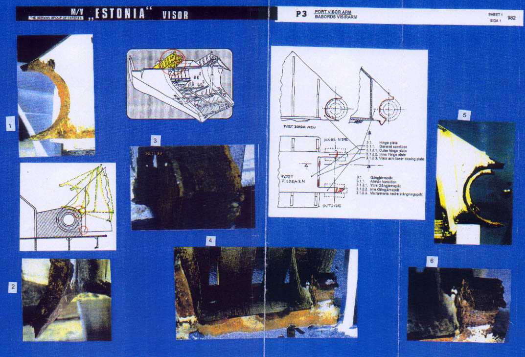
P 3 - Port Visor Arm - Sheet 1
The overview drawing shows the area in question and 3 detail drawings demonstrate the damaged hinge plates. A further detail drawing shows the contact areas between the broken hinge plates and the hinge parts on the forecastle deck during the casualty sequence-of-events. Photographs 1-6 indicate the condition of the broken hinge plates.
In detail:
Pictures:
1 - shows the port outer hinge plate without any hammering marks at the upper and lower fracture areas, the inside without burning marks but still showing the circumferential drilling marks because at newbuilding the holes in the hinge plates were drilled by Meyer Werft - see Subchapters 2.4.2 and 2.4.6.
2 - shows the lower fractured part of the outer hinge plate which is evidently bent to starboard (this according to the metallurgist Prof. Hoffmeister was the last hinge part to break) - see Subchapter 34.4.
3 - shows the inner upper fracture area which evidently had been exposed to hammering.
4 - shows the lower part of the vertical face plate of the visor arm (visor arm lower closing plate) to which the hinge plates are welded. The lower parts of the outer and inner hinge plates can be seen as well. The hammering marks correspond to respective marks on the hinge parts on the forepeak deck - see Subchapter 29.2 - Sheet S 1 / P 1.
5 - shows both hinge plates looking from port to starboard, evidently the inner lower part was severely crushed together and bent downwards by heavy hammering.
Note: When measuring the distances from the vertical welding seams between face plates and hinge plates and the inside of the bores through the hinge plates it becomes evident that at the starboard hinge plates there is about 15 mm less material than at the port hinge plates. This means that the visor was misaligned at least by this distance of 15 mm in the forward / aft direction. See the drawing below.
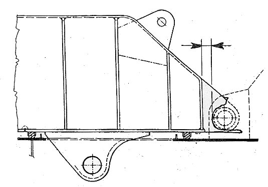
This means that the distance between the 2 arrows above was 15 mm smaller at the starboard hinges compared to the port hinges. This was certainly one of the reasons why the starboard hinges broke first and the port hinges were holding for some time longer.
Consequently the following facts are considered to be established:
(1) The port hinge plates were in a considerably better condition than the starboard ones. The outer one showed no burning but drilling marks, the inner one showed only slight indications of burning.
(2) The inner hinge plate upper part showed minor, the lower part heavy hammering marks. The damage indicates several impacts.
(3) The face plate showed two areas of hammering. The distance between both areas does not coincide with the distance between the hinge plates fitted on the forecastle deck. The port hammering mark is directly adjacent to the outer hinge plate indicating that the visor and vessel were heeled to starboard at time of contact.
(4) The port outer hinge plate was the last one to fail.
(5) The visor was misaligned in forward/aft direction by at least 15 mm.
(click for full
page images)
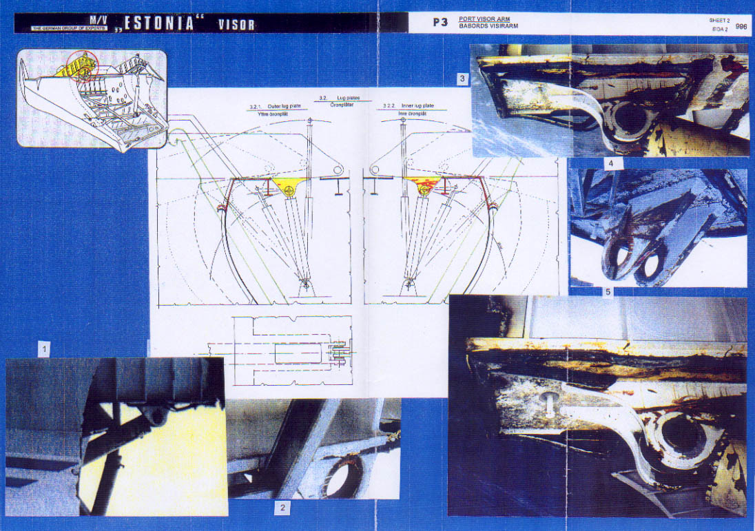
P 3 - Port Visor Arm - Sheet 2
The overview drawing shows the area in question. 2 detail drawings demonstrate the forward/aft movements of the visor after the hinges had failed and the resulting scoring/scraping marks at the lug plates, which are also indicated on 5 photographs.
Pictures:
1/2 - show the outer lug plate of the actuator underneath the visor arm which is evidently completely undamaged with the white paint untouched, which is confirmed by the two pictures below.
3/4/5 - show the
opposite inner lug plate with very deeply engraved scraping marks, furthermore
all three pictures show that the rubber packing, which is supposed to seal
the opening for the actuator in the forecastle deck, is - contrary to the
starboard side - torn and damaged.
This picture
on the next page shows the damaged and torn rubber packing indicating movement
of the visor without this side having been raised up.
The following facts are considered to be established:
(1) The outer lug plate is completely untouched while the inner lug plate shows very deeply engraved scraping marks. This means that at the time when the lug plates were cutting through the deck plating and the deck beam the vessel must have heeled already considerably to starboard. Therefore the centre of gravity of the visor had shifted from forward to starboard and the force direction was no more to forward/downwards but starboard/downwards. Thus the weight of the visor in athwartships direction was now carried by the inner port and the outer starboard lug plates because the locating horns gave no more transverse support as the visor had moved too much forward.
(2) As the lug plates underneath the starboard visor arm were both badly affected, the outside more than the inside, it must be assumed that the starboard hinges failed first. At that time the vessel was only slightly heeling to starboard but rolling and consequently both the inner and the outer hinge plates were affected. The port hinges remained intact for the time being. The starboard side of the visor moved - in slightly raised condition - forward/aft a couple of times when the vessel was still only slightly heeling to starboard and was rolling, whereafter the starboard heel increased considerably and also the port hinges broke. Only thereafter also the port lug plate started to cut first through the deck plating and then through the deck beams. At that time the heel to starboard must have been that big already that the outer port lug plate did not come in contact with the steel parts cut through by the forward parts of both lug plates - see the picture above.
(click for full page images)
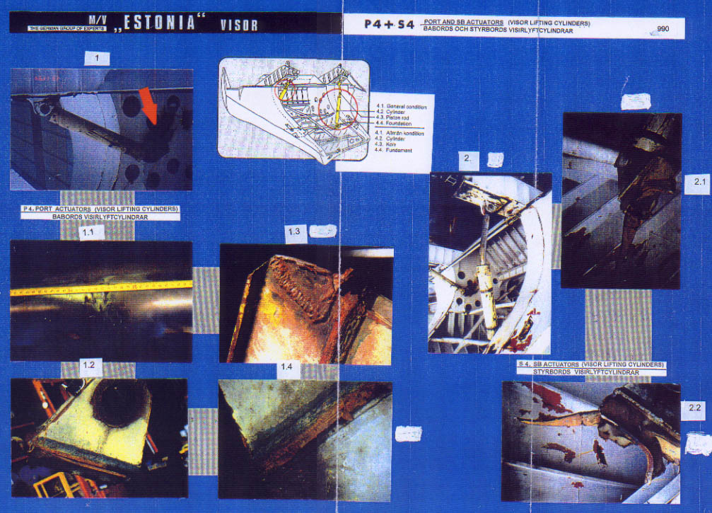
P 4 + S 4 - Port and Starboard Actuators (lifting cylinders)
The overview drawing shows both actuator in as-found condition attached to the visor. 7 photographs demonstrate the condition of the actuators and its foundations, further photos are shown on the following pages.
In detail:
Pictures:
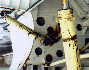
1 - shows the port actuator in jammed condition inside the inner longitudinal bulkhead of the visor. The spherical bearing of the actuator allows a 15° deviation to both sides. The actuator evidently swung into this jammed position after the visor had moved enough forward and after the bow ramp inside the visor was low enough. Thereafter the actuator remained in this position until being dismounted by MacGregor, Turku, in February 1995. The picture below shows the port inner bulkhead after the actuator had been removed.
Measurements revealed and photos confirm that the foundation of the actuator has not been in contact with the plating of the inner longitudinal bulkhead of the visor. Therefore the above visible indentations, scraping and scoring marks have been caused when the visor was hanging on the bow ramp. See also Subchapter 29.2 - The Bow Area - and P 7 further down in this subchapter.
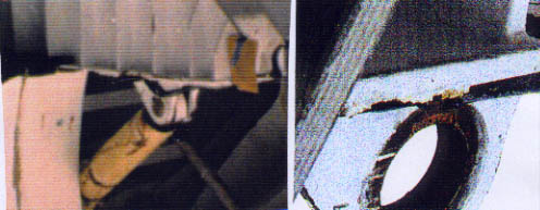
1.1 - shows the piston rod of the port actuator which is deeply scored on the starboard side at a distance of 520-600 mm from the lug plates underneath the visor arm.
Note: The starboard actuator which the JAIC did not consider worthwhile for examination shows less scoring on the piston rod as can be seen on the pictures below.
from starboard side & from port
side
1.2 / 1.3 / 1.4 - show the foundation by which the port actuator should have been connected to B-deck. The pictures demonstrate that the foundation had been temporarily repaired and that the welding connection to B-deck had failed already before the casualty since parts of the welding seam were found to be cracked with oil inside the cracks. According to the observations of truck driver Per-Arne Persson this actuator had been burnt off by flame cutting completely sometime before the casualty and was reportedly not or only rather weakly rewelded to B-deck. See also Subchapter 12.5.
In consequence of
this statement the photos showing the damage condition of this foundation
have been analysed in detail and the result is outlined below:
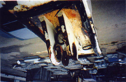
The foundation
of the visor actuators did consist of two strong lugs welded to the B-deck
and which were supported by two longitudinal and two transverse stiffeners.
The picture below shows the port foundation with actuator still attached to
the recovered visor. The arrows indicate the different components.
- arrow 1 = port outer lug plate of actuator foundation
- arrow 2 = port inner lug plate of actuator foundation
- arrow 3 = port inner stiffener (deformed)
- arrow 4 = port outer stiffener
In undamaged condition the arrangement looks as indicated by the drawing below looking from aft to forward, whereby the numbers refer to the previous photo and to the photo below:
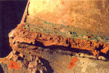
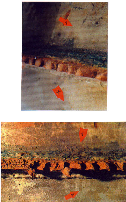
On the above photograph the reader looks on the lower part of the port outer lug plate (arrow 1), i.e. from port to starboard. Arrow 5 points to the remains of the B-deck, to which the port outer stiffener (arrow 4) is still welded. In the forward part of that stiffener an old temporary repair with very poor welding seams is visible (arrow 6). A close-up is shown below.
The lug plate (1) was obviously only partly connected to the B-deck as can be seen from the above photo when it was ripped off the B-deck (5) and only a small part connected by the welding seams (green paint) remained with the actuator foundation. The deck as well as the stiffener were pre-damaged - see Subchapter 34.4 - Enclosure 30.417 - which is indicated by the damage repair, but also by the more or less straight cracking of the stiffener forward and aft of the lug plate, as can be seen on the following photograph.
Due to the relatively straight cracks (7) directly below the forward and aft parts of the lug plates, it has to be assumed that the stiffeners in way were affected by fatigue cracks. The cracks had developed during some considerable time before the casualty due to load changes during opening/closing of the visor and did most probably propagate more quickly during the last month before the casualty because of the increasing difficulties with the visor, especially with the port side. See Subchapter 12.4 / 12.5. The following drawing demonstrates the above.
The following photographs indicate the condition of the B-deck in way of the port visor actuator foundation. The reader looks to the port outer lug plate and follows on the next 4 photos the ripped off B-deck remains from forward to aft of the outer lug plate. For easy reference the photographs are marked with the previously used arrow numbers.
The following photograph shows the actuator foundation after it was removed and taken to the workshop of MacGregor, Turku for examination/testing on behalf of the JAIC. The arrows show the same numbers as used above.
As it is obvious from the close-ups below, the stiffener (3) was hardly spot-welded and thus only slightly connected with the B-deck. As this part of the stiffener is not painted at all - see the next photo to which the reader looks on the port inner lug plate from starboard to port - it is no more original, i.e. has been installed subsequently when the vessel was trading already.
The following photograph shows the port visor actuator foundation after parts had been cut out for testing purposes. The foundation lies on its port outer lug plate. In the front the port outer stiffener (4) is visible, which is fully welded to the B-deck (5). Further at the forward right corner the old temporary repair with the very poor welding seams (6) is visible from inside. For cutting purposes the port inner stiffener (3) had been removed.
The apparent fact that this stiffener (3) had been disconnected from the B-deck (5) respectively since the last repair was never really fitted to it, is further confirmed by a part of the welding seam - see arrow 8 - on the previous two photos - apparently being soaked with oil while the stiffener below is unaffected. This means that this stiffener was not welded to the B-deck.
Consequently the following facts are considered to be established:
(1) The outer stiffener of the port actuator foundation shows an old temporary repair with very poor welding seems in its forward part. Due to the corrosion visible on the previous photos it has to be assumed that this improper repair was carried out already some considerable time before the casualty.
(2) The stiffeners show relatively straight cracks directly below the forward and the aft ends of the lug plates. Therefore it can be reasonably assumed that the stiffeners were affected by fatigue cracks and thus pre-damaged. The cracks had developed during some considerable time before the casualty due to load changes during the opening and closing of the visor.
(3) The B-deck was also affected by fatigue as already explained for the stiffeners. This fact is indicated by the condition of the ripped off deck remains.
(4) The port inner stiffener was no more the original one since firstly it did not show any protecting coating and secondly was only spot welded to the deck - if at all. All stiffeners were however fully welded to the deck by the shipyard during new-building, as it can still be seen on the starboard actuator foundation.
(5) The load carrying capacity of the port visor actuator was considerably reduced.
There is, however,
another remarkable difference between the condition of the port and starboard
actuators, viz.
- MacGregor,
Turku has examined the port actuator upon instructions of the JAIC and found
among other things that
"... it was noticed that there were heavy damages at the distance when the piston rod is about 400 mm open. The damages were on the starboard side of the piston rod. Damages were also noticed on the piston cover's fixing screws. The ends of these hexagon screws were like hammered." (See Enclosure 29.413)
The picture below demonstrates the above.
This is different
at the starboard actuator as can be seen from the pictures on the next page
with close-up of the area of interest. The arrow 1 points to the hexagon screws
looking absolutely identical and which are evidently not hammered at all.
Arrow 2 points
to a clamping ring in apparently undamaged condition which had obviously not
been exposed to hammering or otherwise heavy contacts. The differences between
the external conditions including the hexagon screws of the port and starboard
actuators can be explained as follows:
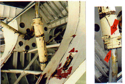
- The port actuator: Cover and hexagon screws on the piston rod side are severely hammered. The clamping ring is missing. The outside of the actuator shows heavy longitudinal scoring marks. The piston rod shows heavy damage on starboard side at a opening stage of ca. 400 mm.
The MacGregor Report - see Enclosure 29.413 - concludes:
"By the a.m. report we can see that the lifting cylinder has been opened at least about 400 mm and there has been very high pressure on the piston rod side."
This means that it was tried manually to hold the visor down by hydraulic pressure on the piston rod side.
- The starboard actuator: Cover and hexagon screw on the piston rod side were not affected at all. The clamping ring was still attached to the piston and apparently completely unaffected. The actuator shows only very few external scoring marks - see picture above. The piston rod shows some scoring marks but no particular damage, certainly no heavy damages on the starboard side as can be seen on the piston rod of the port actuator. The scoring marks on the piston rod may have been caused at any time during the long process of separation from the vessel. This does not allow the conclusion that the lifting cylinder had been opened when the actuator was still attached to B-deck, i.e. that the visor opened to some extent, although this has to be assumed because of the unaffected rubber packings around the actuator opening - see above.
Consequently the following facts are considered to be established:
(1) The port actuator was found in subtracted condition although having been pulled off B-deck and through the front bulkhead by the forward moving visor. Thus it must have been under pressure at or just before the time of the casualty, most likely because the crew was trying to hold down the visor by the actuators but the port one broke off due to the poor connection to B-deck.
(2) This was confirmed when the port actuator was dismounted and examined by MacGregor, Turku who found that "the lifting cylinder had been opened at least 400 mm and that there had been very high pressure on the piston rod side".
This means pressure from upside to downside, which would be used to hold the visor down hydraulically.
(3) The port actuator was obviously pulled through the port front bulkhead of the vessel when it was still intact - see also Chapter 29 - P 4 - by the forward moving visor, the cylinder cover with hexagon screws on the piston rod side being the thickest part with direct contact to bulkhead and internals during the breaking through process. Therefore cover and screws show severe hammering marks and the clamping ring is missing which was probably stripped off the piston when it was pulled through the bulkhead. Also the damage picture of the port front bulkhead - see P 4 in Chapter 29 - does confirm the above because only a metal strip with the approximate breadth of the actuator was clearly cut out of the bulkhead plating and rolled together at the lower end.
(4) Evidently all this was not the case with the starboard actuator, viz. piston cover and hexagon screws show no sign of hammering or any other damage, the clamping ring is in place, the actuator hardly scored. Obviously this piston had not been pulled through the starboard front bulkhead when it was still intact, but when the actuator was pulled through the front bulkhead by the forward moving visor this bulkhead was already open - see Chapter 32 - and therefore the actuator could easily slip through the wide opening - see also Chapter 29 - S 4.
(5) The piston rod of the port actuator shows severe damage on the starboard side at an opening stage of about 400 mm which indicates that vessel and visor were heeled to starboard when the piston rod was extended by 400 mm.
(6) Similar damage cannot be traced at the piston rod of the starboard actuator.
(7) The foundation of the port actuator had been temporarily repaired in a poor and unprofessional way without informing, thus without approval, of the class. It was furthermore cut off B-deck at some time before the casualty and apparently refitted improperly to B-deck which explains its early failure.
(8) The foundation of the starboard actuator was apparently properly connected to B-deck and broke only after having been exposed to considerable additional forces. - See Chapter 32.
(click for full
page images)
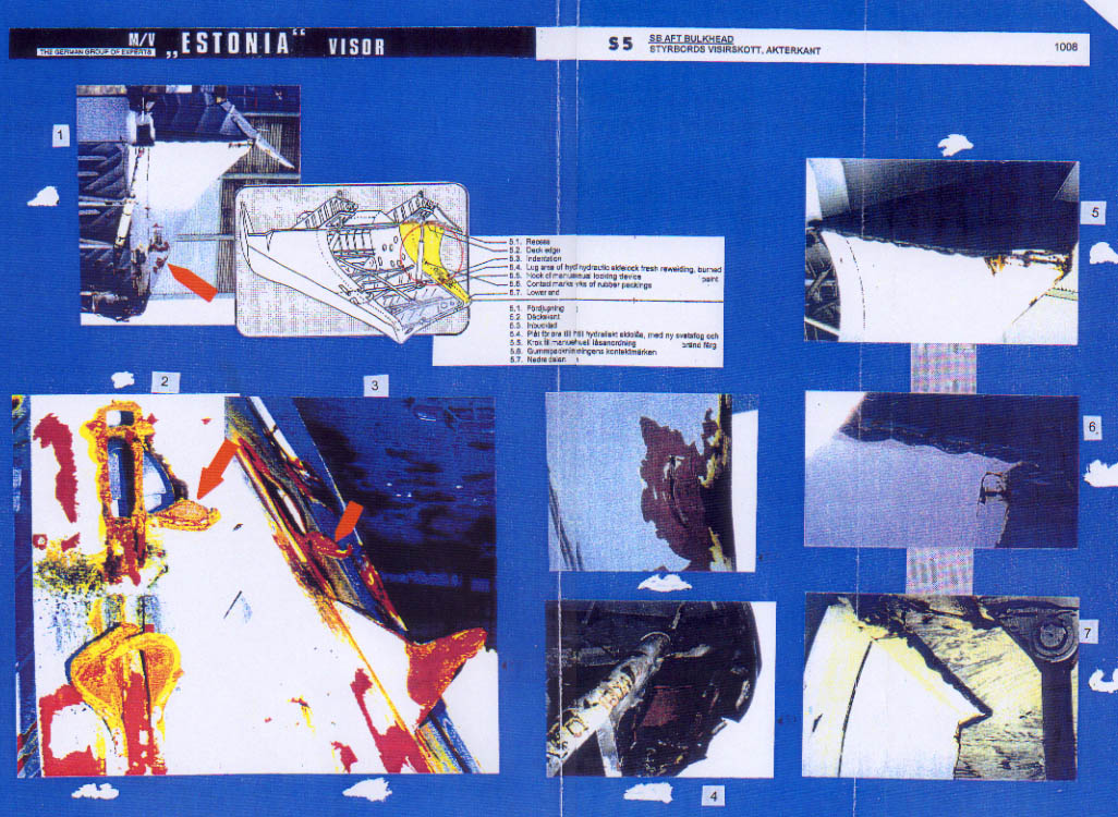
S 5 - Starboard
Aft Bulkhead
The overview
drawing shows the area of interest and arrows point to the items to be demonstrated
by 7 photographs.
Pictures:
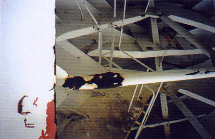
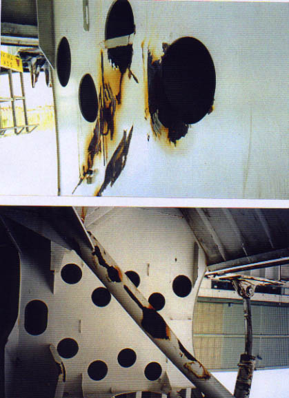
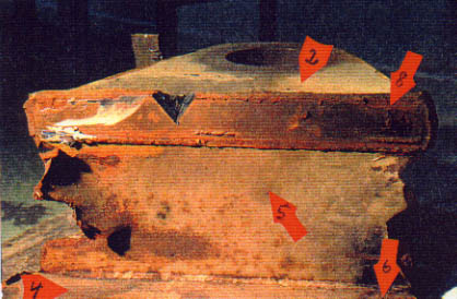
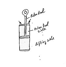
1 - shows the starboard aft bulkhead of the visor in total with the opening in the plating, to where the lug of the hydraulic side lock has been welded, further the bent hooks of the manual side lock. A further damage - see arrow and picture 1.3 - was probably caused by the foundation of the starboard actuator after having separated from B-deck.
2, 3 - show the area of the missing side lock lug and the considerably bent hooks of the manual side locks from the top and from the side. The side view shows that the area in way of the pushed out steel tongue - see arrow 1 - is bulged outwards indicating pressure from inside to outside, whereas the plating between the hole for the lug and the hooks shows smoke marks, which are explained in Chapter 32. Around the opening for the lug burning/welding marks from the cutting off and the subsequent rewelding of the lug are visible. The following picture has been taken from the JAIC Report and clearly confirms the above.
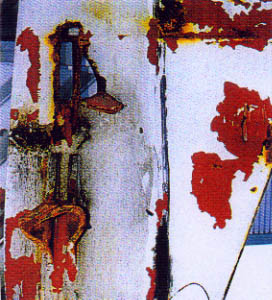
The picture below taken on 23.11.94 shows the lower part of the starboard aft visor bulkhead including the area under discussion looking downwards which is obviously very dark.
Note: According to the observations of previous passengers, for example truck driver Torbjörn Cederqvist - see Enclosure 12.4.3.157 - Subchapter 12.4 - both lugs had frequently been burned off when the crew was unable to open the side locks hydraulically upon arrival in Tallinn. Obviously they were subsequently rewelded to the same location.
It is also obvious from the condition of the starboard lug as can be seen from the two video images of the corresponding lug still attached to the bolt on the wreck that the lugs had been repeatedly cut off and rewelded.
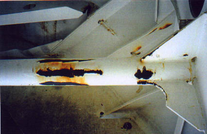
The very thick welding seam on the lower part - see arrow 1 - is actually a build-up of several welding seams, i.e. weld on top of the previous weld without grinding away of the remnants. It is obvious that the bulkhead part attached to the lug - see arrow 2 - had not been torn out of the bulkhead during the casualty scenario but much earlier because, due to the thickness of the accumulated welding seams, this original part of the visor bulkhead (Viking Line colour) could not come in contact with the adjacent visor plating. Consequently, it has to be assumed that each time the lug was cut off by burning it was just stuck into the respective hole in the bulkhead and welded from both sides, if at all - see also Chapter 29 - S 4.
The next pictures - also taken from the JAIC's Report - show the upper parts of the holes in the visor bulkheads where the lugs had been fitted.
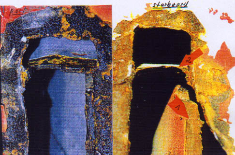
The analysis and comparison of both pictures reveal the following:
(1) The plating around the port holes is unaffected. Some remains of welding seams are visible at the upper right corner and at the right (inside) there are indications that welding seams could have been there. At the outside (left side) there are no such indications which refers also to the upper hole. Only few spots of corrosion can be seen. In summary it has to be assumed that the lug had not or only to a very limited extent been welded from the outside.
(2) The plating around the starboard opening looks completely different because the plating is distorted, the stiffener at the inside is torn off the bulkhead, the plating had apparently been exposed to heat and subsequently became corroded. The steel part between the small hole and the bigger opening was pushed upwards, obviously by the lug then and still attached to the vessel, i.e. the visor made a downward movement in relation to the lug, i.e. the vessel. Thereby the lug was pressed into said steel part. The indication of the remnant of a welding seam is visible at the upper right corner of the big opening. Otherwise there are no indications of welding seams at all.
(3) The lugs of the visor's side locks were obviously not welded to the plating, but there were permanent holes in the plating of both sides through which the lugs were stuck and welded from the inside only. Thereby it was possible to adjust the part of the lugs extending the plating to the length required by the ever changing misalignment of the visor.
The discussion of the pictures on Sheet S 5 is continued:
Pictures:
4 - shows the lower aft part of bulkhead/bottom in severely damaged condition which will be explained in Chapter 32 as the port is unaffected.
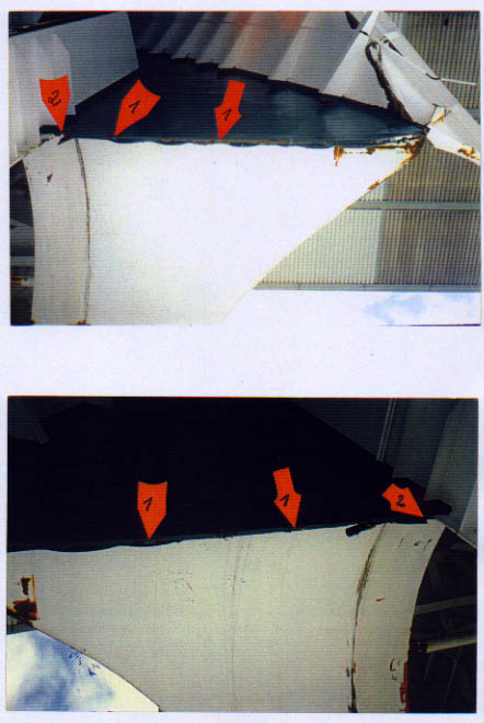
5, 6, 7 - show the upper part of the aft bulkhead with the forecastle deck and the recess - see arrows - apparently affected by the visor moving forward / aft after the visor hinges were broken and the vessel already had a starboard list.
In addition, attention has to be drawn to both aft parts of the visor deck shown on the two pictures overleaf. The corroded areas indicated by arrow 1 on both sides have been the spots where the visor had been welded to the vessel at the time when the bushings of the starboard visor hinges were renewed. This was the time when ESTONIA berthed in Tallinn stern first - see the statement of Torbjörn Cederqvist - Enclosure 12.4.3.157 and Subchapter 12.4.3 - the cars left the ferry via the stern ramps instead of the bow ramp as it is normally the case in Tallinn.
Arrows 2 on both sides indicate the corner between visor deck/aft bulkhead and visor arms along which the rope was running by which the bow ramp was kept close as tight as possible. The drawing below show the forecastle deck with the two winch drums by which the rope was heaved tight and the two fairleads around which the rope was running.
Consequently the following facts are considered to have been established:
(1) The lug of the hydraulic side lock had been cut off and rewelded only from the inside several times without grinding off the remnants of the previous welding seams. This led to a build-up of thick welding seams, which reduced the load carrying capacity of this lock to a fraction of the original.
(2) The plating around the pocket for the locating horn was unaffected.
(3) The area around the lug of the side lock was pushed out, is distorted and was exposed to heat.
(4) The area between the initial lug location and the bent hooks show intense smoke marks.
(5) The lug separated from the visor bulkhead when the visor was in a forward/downward movement.
(6) The hooks were crushed together in such a way which cannot be explained mechanically.
(7) The bottom end of the aft bulkhead is partly crushed, partly torn and on the outside a deep fold in way of the contact area with the rubber packings of the corresponding front bulkhead of the vessel extends from the area of the lug down to the bottom area. - See the right picture on the next page. The corresponding area on the lower part of the port aft bulkhead of the visor, as can be seen on the left picture on the next page, is apparently undamaged.
(click for full
page images)
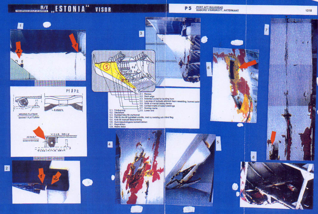
P 5 - Port Aft
Bulkhead
The overview
drawing on sheet P 5 shows the area in question on which 8 arrows point to
the areas of interest. 3 detail drawings demonstrate the as-built and as-found
conditions of the flatbars with rubber packings underneath the attends of
the visor deck which was overlapping the forepeak deck. The condition of the
port aft bulkhead is explained by means of 8 pictures on the sheet and some
additional photos incorporated into the text.
In detail:
Pictures:
3 - shows the port
aft bulkhead as a whole with no damage except the punched-in plating below
the pocket for the locating horn - see picture 4 from the outside and picture
5 from the inside. The damage picture indicates several contacts between
visor plating/locating horn which are only possible if either the hinges are
already broken and the visor was raised by ca. 100-150 mm only, or if the
visor was misaligned by this distance, which it was during the last month
before the casualty - see the statement of Bo Pettersson, Enclosure
12.4.3.157.1, and Subchapter 12.4.3.
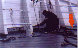
According to
the observation of Bo Pettersson the port outer edge of the visor was extending
the forecastle deck to such an extent that he could see the water through
the gap. He estimated the difference between visor and forecastle deck to
have been about 100 mm. Although crew members hammered with sledge hammers
on the edge, the condition did not change and they gave up.
The image following
shows the area in question. The arrow indicates where the crewman was hammering.
The consequences
of such a vertical misalignment between port and starboard in combination
with a forward/aft misalignment, as explained on the previous pages, are grave
because nothing fits anymore as will be explained in the following:
(a) The locating horn does not reach its pocket anymore and caused damage to the plating below - see picture 4 - which was tried to be rectified by welding doubler plates - see picture 5 - below the holed plating and the picture below.
arrow 1 = opening cut around the holes where the lug had been located
arrow 2, 3, 4 = doublers fitted
arrow 5 = buckled bracket
The fitted doublers and the buckled bracket points to an area exposed to high stresses and apparently also to damage which has certainly to be seen in connection with the severe misalignment of the visor.
Note: When the visor was examined by members and consultants of this 'Group of Experts' the JAIC was asked for permission to remove the doublers to see what is below. Permission was, however, not granted.
(b) The visor deck plating (arrow 1) of the edge with the visor arm (arrow 2) is cracked - see picture 2 and comments on the previous pages.
(c) The flatbars housing the rubber packings below the recess of the visor deck extending to the forecastle deck were hammered flat - see the drawing between pictures 1 and 2.
(d) The starboard locating horn and the pyramid on the forepeak deck do fit into their pockets only with difficulties (visor was opened/closed frequently - see Subchapter 12.4 - before the pyramid fitted into the pocket).
(e) In summary it must have been very difficult to close the visor and even more difficult to lock the locking devices and open them subsequently. It has been confirmed by many previous passengers that the crew was unable to open the locking devices, neither hydraulically nor by force - see Subchapter 12.4 - and then the next step was to take the burning gear and cut off the lug. Subsequently the lug was rewelded time and again and apparently only from the inside of the visor but always without grinding off the old remnants, in other words: totally improfessional.
This confirms the
observations of passengers on previous voyages - see Subchapter 12.4 - that
the lugs of the side locks were frequently cut off by means of burning gear
when the crew were unable to open them.
The following
image shows the lug attached to the bolt inside the vessel before it was pulled
out by the diver. Contrary to the starboard side this lug rested inside the
bulkhead as visible, although it was on the high port side.
The next image shows the same lug after having been pulled out by the diver. Arrow 1 indicates the very thick accumulation of welding seams and arrow 2 indicates the bulkhead part torn or cut out at some time before the casualty.
The hooks for the manual side lock were just bent together, as can be seen on the picture on the next page. The area around the lug location shows burning marks obviously from cutting off the lug by flame cutting - see arrow - but no smoke marks as on the starboard side and the plating was not pushed out/distorted.
The commenting of the pictures on Sheet P 5 is continued:
Pictures:
7 - shows the rubbing
marks from the rubber packings at the vessel's front bulkhead which are straight
in the upper part and slightly irregular in the lower part. The picture on
the next page shows the lower port aft bulkhead. It becomes evident that the
area below the pocket for the locating horn does not show any rubbing marks
- contrary to the starboard side - which leads to the conclusion that the
rubber packings at the front bulkhead of the vessel were missing also in this
important location - see arrow 1.
The pressure
mark of the locating horn inside the pocket - see arrow 2 - indicates pressure
on the visor from port to starboard, which is a further indication for the
severe misalignment of the visor.
Arrow 3 indicates a damage apparently caused when the visor fell off the bow
ramp in the final stage when the heel of the vessel was already 120°/130°
to starboard. This will be further explained in the following item 6 -
The Visor Bottom.
8 - shows the lower aft bulkhead/visor bottom which is only moderately damaged compared to the starboard side - see also the picture below.
The arrow points to a damage to the port aft edge of the visor bottom which apparently occurred when the visor moved transversely from port to starboard. This will be explained in Chapter 31 - The Casualty Scenario. See also picture 5 on the following Sheet 6.
1 - shows the upper part of the aft bulkhead with the moderately affected recess which has already been discussed at the beginning of this item. The picture on the next page shows the recess as enlargement with damage at the edge of the shell plating - see arrow - which obviously occurred when the visor was moving in the transverse, i.e. athwartships, direction. - See also Chapter 31 - The Casualty Scenario.
2 - shows
the corner between forecastle deck and visor arm - see the arrow 1 on picture
1 and the arrows 1 and 2 on the close-up - picture 2 - which were discussed
already at the beginning of Sheet P 5.
Evidently something
solid had been underneath this corner when the visor was closed which caused
the deck edge to crack and to be bent upwards.
The following facts are considered to be established:
(1) Due to the vertical misalignment of the visor the port side of the visor was raised by 100 or more mm which made it impossible for the locating horn fitted at the port front bulkhead of the vessel to enter the mating pocket of the visor. Instead contact occurred in the area below the pocket - as the visor was raised - and the plating became damaged.
(2) The crew fitted several doublers and support brackets in way to compensate for the stress created by the misalignment.
(3) The lug of the hydraulic side lock including the plating part to which it was welded had apparently been cut off and rewelded several times without grinding off the remnants of the previous welding seams. This led to the very thick welds with substantially reduced load carrying capacity of the side locking device of the visor.
(4) The rubber packings in way of the area below the pockets for the locating horn were either missing at the front bulkhead of the vessel or had not been in contact with the corresponding parts of the visor bulkhead due to misalignment.
(5) The area around the location of the lug of the hydraulic side lock is not pushed out, nor do smoke marks exist.
(6) The hooks of the manual side lock are just slightly bent together.
(7) The recess at the upper part of the port aft bulkhead of the visor was damaged when the visor was moving transversely respectively athwartships.
(8) The lower part of the aft bulkhead is not affected.
(9) The plating between forecastle deck and visor arm is cracked and the steel pads protecting the rubber packings were hammered flat by crew members attempting to lower down the port side of the visor which was extending the forecastle deck of the vessel by 100 mm or more.
(click for full
page images)
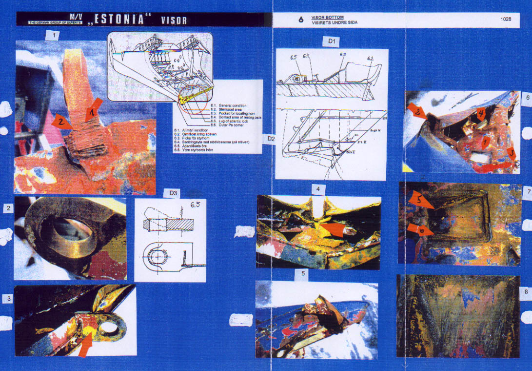
6 - Visor Bottom
The overview drawing indicates the area in question in yellow and 6 arrows
point to the area to be explained, viz.
1 - The general condition of the bottom
2 - The stempost area
3 - The pocket for the locating horn
4 - The contact area of resting pads (from the forepeak deck)
5 - The lug of the Atlantic lock
6 - The outer port edge
Detail drawing D1 explains the misalignment of the visor in forward/aft direction, D2 the indented visor bottom and D3 explains the way the visor lug of the Atlantic lock was bent. 3 pictures demonstrate the condition of this lug, 3 others the condition of the visor bottom and 2 further pictures show the inside of the pocket in the visor bottom to take-up the pyramid on the forepeak deck when the visor was closed.
Note: This pocket was the mating part of the locating horn - the pyramid - on the forepeak deck. The pyramid guided the visor in transverse direction which became increasingly difficult during the last month before the casualty.
In detail:
Pictures:
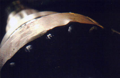
6 - shows the pressed in visor bottom with the pocket for the locating horn (pyramid) - see arrow 1 - the gap in the stempost area - arrow 2 - the visor lug - arrow 3 - and the damage caused by the pyramid after the visor had moved to starboard - arrow 4.
In the opinion of this 'Group of Experts' the bottom had been held back by the Atlantic lock until it finally also broke when the visor fell to starboard until it rested on the bow ramp. - See Chapter 31. - It is also obvious that the visor had overlapped the forepeak deck considerably to the effect that the forepeak deck had penetrated the inside of the visor bottom up to ca. 0.5 m. This must have given the visor the main support against falling off to starboard, because the bow ramp alone could not have carried the entire weight of the visor after the Atlantic lock had failed. - See Subchapter 34.5. - The damage picture of the strong ice strengthened hull plates on both sides of the collapsed stempost do confirm the above. See arrow 2 and also Chapter 31 - The Casualty Scenario.
7/8 - show the inside of the pocket for the locating horn on the forepeak deck - the pyramid - with contact marks of different depth at port and starboard side - see arrows 5/6. The scoring marks enlarged on picture 8 indicate visor movements from starboard forward to port aft whereby the pyramid only came in contact with the aft half of the pocket due to the extensive misalignment of the visor as demonstrated by the detail drawing D1 - on Sheet 6.
4 - shows the deeply pressed in visor bottom as indicated on detail drawing D2 on the Sheet 6 with the stempost folded backwards - see arrow - and the respective gap in the shell plating created by contact with the ice knife on top of the bulbous bow.
5 - shows a very sharp damage to the port aft edge of the visor bottom which probably occurred due to contact with the bow ramp when the visor moved transversely, i.e. athwartships in the final stage of gliding off the bow ramp and forepeak deck. - See also Sheet P 5 and Chapter 31.
1 - shows the visor lug being part of the Atlantic lock. Arrow 1 points to the previously burnt off part of the lug with cracks propagating from burning marks (arrow 2). The lug apparently became twisted to starboard when the visor moved abruptly to starboard until its port inner bulkhead rested on the port side of the bow ramp. The deep crack in the bottom of the visor to port of the lug confirms this. It further indicates that the visor lug was about to crack off the visor bottom when the lugs on the forepeak deck failed first. This is underlined by the impressive picture below indicating an upwards and to starboard movement of the visor when this big crack propagated and came to a stop when the lugs on the forepeak deck failed.
2 - demonstrates the elongation of the lug which is partly due to wear over 141/2 years and partly due to manipulation by Christer Koivisto already in 1982 - see Chapter 12.4.
3 - shows the yellow basic primer - see arrow - used in the whole foreship area by the Yard during newbuilding.
Note: The basic primer of the starboard lug of the Atlantic lock was analysed on behalf of the JAIC and found to be grey.
The following facts are considered to be established:
(1) The visor bottom had overlapped the forepeak deck which penetrated deeply into the bottom structure of the visor which supported the visor during the increasing heel of the vessel.
(2) The gap in way of the collapsed stempost of the visor was caused when this part fell on top of the ice knife on top of the bulbous bow. The very strong ice plates consequently bent up to both sides of the collapsed stempost provided further support to the visor and also prevented its falling off to starboard.
(3) The scoring/scraping marks inside the pocket for the pyramid do confirm the vertical and forward/aft misalignment of the visor.
(4) The very sharp damage at the port aft edge of the visor bottom was caused when the visor moved athwartships in the final stage of gliding off the bow ramp, the forepeak deck and finally the bulbous bow to the bottom of the sea.
(5) The visor lug of the Atlantic lock almost cracked off at the bottom when the visor moved forwards and to starboard, however, then the lugs of the forepeak deck broke first and the crack propagation stopped.
(6) The visor lug was considerably elongated due to wear in 141/2 years of exposure to changing loads and the manipulations by Christer Koivisto.
(7) The basic primer of the visor lug is yellow which is an indication that it is still the original lug as the initial primer at newbuilding was of such colour. See also Subchapter 2.4.6. The basic primer of the starboard lug of the Atlantic lock was found to be grey by the JAIC which is a further confirmation that this as well as the other two lugs were not the original ones anymore.
(8) The stempost was cracked 4 times well before the casualty and the crack had penetrated the stempost up to 50% of its thickness at the time of the casualty.
(click for full
page images)
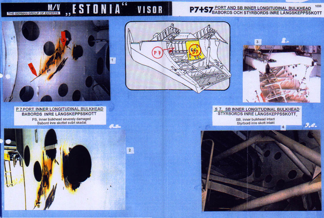
P 7 + S 7 - Port
and Starboard Inner Longitudinal Bulkhead
The so
much different condition of both bulkheads is demonstrated by 2 photographs
each which are explained as follows:
Pictures:
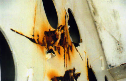
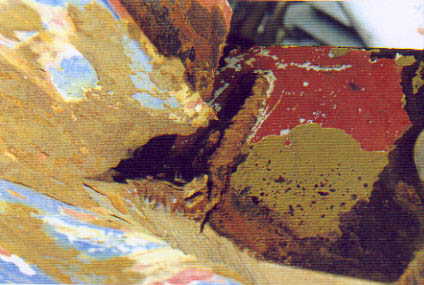
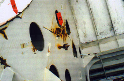
1 / 2 - show the port inner longitudinal bulkhead with scraping/scoring marks at the lower aft part - see arrow 1 - and very deep indentations with the steel plating partly torn - see arrow 2 - and enlargement picture1.1. The picture below shows that the plating was actually pressed into the bulkhead up to 120 mm.

It is quite obvious that these deep indentations cannot have been caused when the port actuator was swinging inside the longitudinal inner bulkhead (due to the existing starboard list of visor and vessel) and got jammed there, as evident from the picture below.
After the actuator had been dismounted by MacGregor, Turku in February 1995 the area looked as it is shown by the following picture. Arrow 1 indicates the area at the edge of aft and inner bulkheads where the aft bulkhead is slightly extending the inner bulkhead and where metal parts were torn off when the actuator moved into its jammed positions. A detailed evaluation of this and other pictures did reveal that neither the actuator nor its foundation had come in contact with the bulkhead which is due to the angle between the fastening point at the lugs below the visor arm and the bulkhead edge. The actuator was able to swing into this position because of its spherical bearings which allow deviation of up to 15° to each side.
It is thus proven with sufficient certainty that the severe damage as well as the scraping and scoring marks were only caused by the bow ramp then lying inside the visor on the beam structure and the visor resting on the bow ramp in way of the damage area under discussion. This shall be explained in more detail in Chapter 31 - The Casualty Scenario.
The picture below shows the port inner side of the visor with the slightly damaged frames at the port aft part of the ramp house. The upper part of the longitudinal bulkhead is completely unaffected. The scorings and the deep indentations and deformation (arrow 2) are restricted to the middle part, and, in the foreground, the vertical beam which had been in contact with the upper part of the ramp with the folded flap in between is visible (arrow 1).
1 / 2 - show the completely intact and untouched starboard inner longitudinal bulkhead which - due to the starboard heel - remained obviously unaffected even during final separation of visor and bow ramp which will be explained in Chapter 31 - The Casualty Scenario.
Consequently the following facts are considered to be established:
(1) The upper and the lower parts of the port inner bulkhead of the visor are completely unaffected, the middle part however is very severely scraped, indented and cracked which was caused by the bow ramp when the visor was resting on it.
(2) The above-mentioned damage was exclusively caused by the bow ramp, the port actuator has not been in contact with the bulkhead plating.
(3) The opposite starboard inner longitudinal bulkhead is completely unaffected, thus there has been no contact with the bow ramp.
(4) The above explained severe damage at the port inner longitudinal bulkhead in connection with corresponding damage at the port bow ramp - see Subchapter 29.2 - The Bow Area - and witness evidence - see Enclosures 29.6.414 / 29.6.415 - confirms that the visor had been resting on the bow ramp which caused the damage to the port inner bulkhead.
(5) Due to the absence of damage/scorings forward and aft of the existing damage approximately in the middle of the port inner bulkhead it has to be assumed that the visor fell off the bow ramp / forepeak deck towards the starboard side by force of gravity once the heel was sufficient, i.e. 130°/140°.
(click for full
page images)
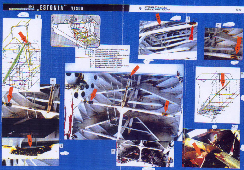
8 - Internal
Structure
The overview
drawing indicates the area of interest, i.e. the 3 transverse - and the 2
vertical beams called pipe girders on the overview drawing. 5 arrows point
to the areas to be explained. The explanations are assisted by 2 detail drawings
- Nos. 3 and 8 - and 7 photographs.
In detail
Pictures:
1 - shows the view
into the visor inside with the 1st stringer above and the 2nd stringer below,
the port and starboard longitudinal bulkheads in their respective conditions
and the vertical beam as well as the cross-beams. Arrow 2 indicates the area
on the vertical beam which took the main weight of the ramp. Arrows 1 and
3 indicate the damage respectively scoring marks on the cross-beam which cannot
have been caused by the bow ramp at the early stage, because there is no corresponding
damage at the ramp and, also, the lower parts, being almost at the underside
of the beam, are unreachable for the bow ramp under any condition.
The explanation
for these marks respectively damage on the cross-beam on both sides can be
seen on the drawing 3., i.e. contact with the bell cranks on both sides at
the top of the ramp already before the casualty when the visor opened/closed
due to the slightly open and misaligned ramp (could no more be properly closed)
and the misaligned visor. In particular the port bell crank is damaged very
severely which was, of course, mainly caused by the contact with the port
inner bulkhead of the visor. On the other hand, it has to be assumed that
this already existing damage was exaggerated when the ramp was inside the
visor and the visor hanging on the ramp.
2 - shows the lower inside of the visor with the lower transverse beam in way of the 3rd stringer. This beam was found to be very severely scored and scraped, which was most probably caused during the lifting operation. The picture also demonstrate the very severely set up visor bottom which is underlined by the close-up No. 10 and explained by detail drawing No. 8. There are two further contact marks in way of the deck beam at the lower forward part of the ramp house, viz. in the most port and most starboard frame spaces, which were evidently also caused by the bell cranks of the ramp when the visor moved further forward and downwards and the vessel was already severely heeled to starboard already. See also sheet 2 - The Ramp House. The picture below indicates the short distance to the port bulkhead because of the starboard heel.
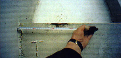
The picture below shows the starboard side with the longer distance to the starboard bulkhead also due to the starboard heel of visor and vessel.
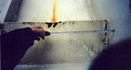
The two pictures below show the damage to the top and port side of the vertical beam.
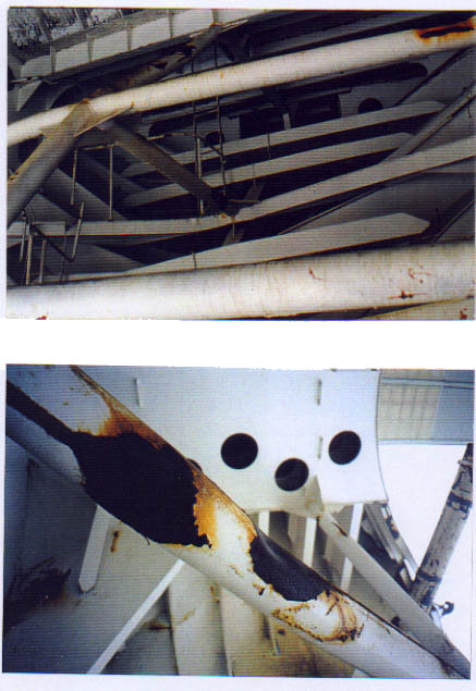
Consequently the following facts are considered to be established:
(1) The upper cross-beam shows damage at two locations on the port side which cannot have been caused by the bow ramp, because there was no corresponding damage at the ramp.
(2) The damage on the port side of the upper cross-beam and the scraping marks on the starboard side were caused during opening/closing of the visor by the bell cranks fitted on both sides at the top of the bow ramp.
(3) The damage to the vertical beam was caused when the ramp was resting inside the visor on this beam with a flap in between. This flap in the centre line of the ramp is heavily damaged.
(4) The vertical beam as well as parts of both sides of the 2nd stringer and the adjacent frames are thickly covered with hydraulic oil. It has not been possible so far to verify from where this oil originates and what caused this quite substantial spill.
(5) There are two contact marks at the deck beam below the forward part of the ramp house, one at the starboard and one at port. The port one is closer to the adjacent bulkhead than the starboard one indicating that the contacts occurred when the visor was heeled to starboard and resting on the bow ramp. The contacts occurred with the bell cranks of the bow ramp when the bow ramp was pushed upwards.
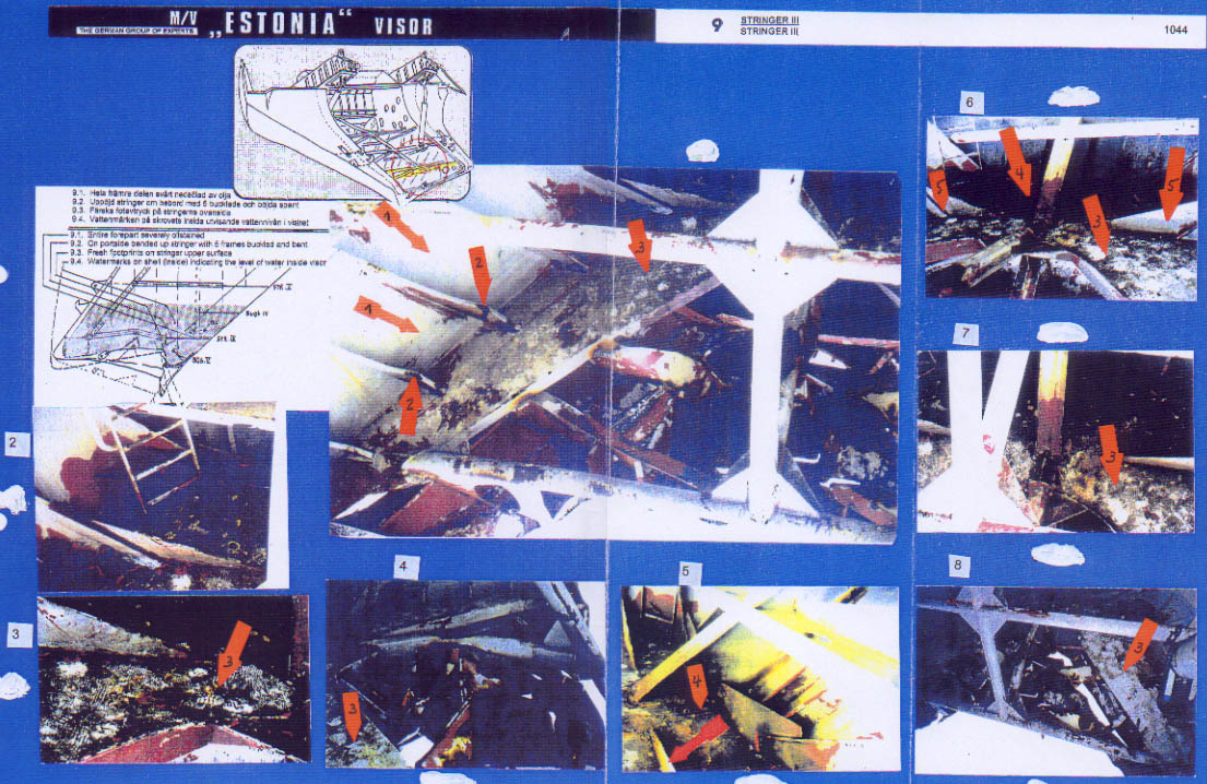
(click for full
page images)
9 - The 3rd Stringer The overview drawing shows the area in question which is explained by 1 detail drawing and 8 photographs.
In detail:
Pictures:
1 - shows a view into the port lower side of the visor with the 3rd stringer, the vertical and transverse beams and the set-up visor bottom. Arrows 1 are pointing to the different watermarks which indicate the heights of water inside the visor at different times and outside water level heights. Arrows 2 are pointing to the buckled frames which indicate that the whole stringer is set up. Investigations have revealed that this damage is of old origin. Arrows 3 indicate the oil on the stringer with the very clear footprints all over the stringer.
2, 3,6, 7 - are detail photos from the above.
6 - shows that the fore part of the 3rd stringer is apparently severely oil stained and picture 5 shows the area at a later stage and better illuminated. Apparently the hydraulic oil floating on top of the water inside the visor and which settled down on the stringers and elsewhere when the water flowed out of the visor accumulated in the forward part of the 3rd stringer - see arrow 4, apparently because this part of the visor was deeper than the aft part which must have been the case for a longer time already because the brackets at both sides of this area (arrow 4), which are indicated by arrows 5, are white and not oil stained. - See also Subchapter 12.4.3.
4, 8 - show the visor bottom which has been commented already.
Consequently the following facts are considered to be established:
(1) The visor's fore part had been lower than the aft part since some considerable time before the casualty which is another confirmation for the severe and increasing misalignment and deformation of the visor.
(2) The port area of the 3rd stringer was severely set up with the frames buckled since some time before the casualty probably the ice winter 1994 when the vessel frequently forced ice. This damage extended up to the 2nd stringer and into the adjacent frames and brackets.
(3) The visor had always been full of water to the outside level when the vessel was at sea. See the photo below.
(4) The hydraulic cylinders/pipes were leaking which caused hydraulic oil to swim on the water surface inside the visor which settled down once the water left the visor.
(5) People had been very active inside the visor, in particular on the 3rd stringer. The majority of the footprints are fresh and not covered by oil, thus originate from the time before arrival and after departure Tallinn on September 27, 1994.
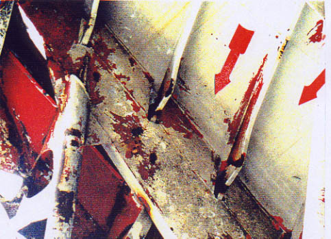
![]()