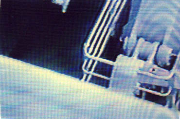
On the evening of 17.09.94, i.e. 10 days before ESTONIA's last departure from Tallinn, a Swedish passenger was standing on the forward open part of deck 7 and filmed the closing of the visor, the handling of the mooring lines by the deck crew and, finally, he zoomed in on the starboard visor hinges. The first copy of the original film was made available to this 'Group of Experts' and a first internal analysis revealed that the starboard visor hinge was in an absolutely disastrous condition as can be seen on the image below.
In order to have this condition properly and professionally evaluated an documented the English military reconnaissance systems consultant Bryan E. W. Roberts from Churchgate/Suffolk was requested to do this.
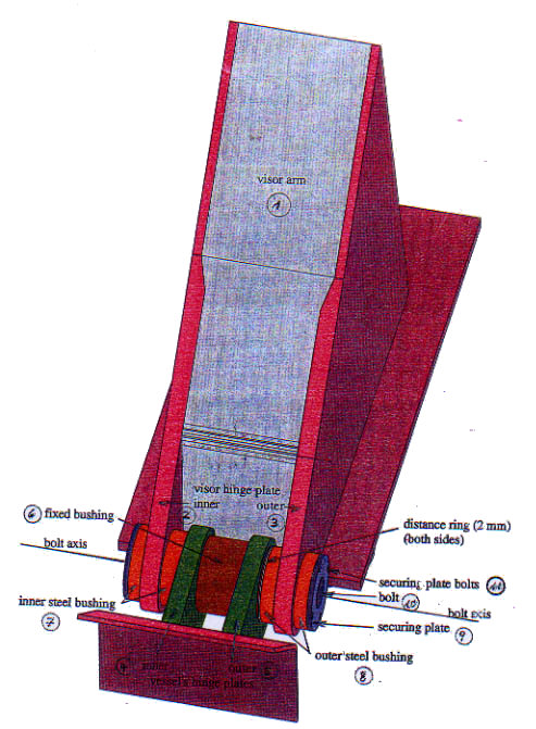
For explanation purposes a computer drawing of the hinge arrangement was made and the figures 1 - 12 point to the relevant components as outlined below:
1 Visor Arm
2 Inner Visor Hinge Plate
3 Outer Visor Hinge Plate
4 Inner Vessel Hinge Plate
5 Outer Vessel Hinge Plate
6 Fixed Bushing
7 Inner Steel Bushing
8 Outer Steel Bushing
9 Securing Plates (both sides)
10 Visor Arm Bolt and Bolt Axis
11 Securing Plate and 4 bolts (both sides)
12 Distance Ring (both sides)
The results are summarised in the Report on the Loss of the Ro-Ro Ferry "Estonia" - attached as Enclosure 12.5.180 and shall be briefly commented as follows:
The object of the
report was to detect and identify any structural rupture or damage which could
have contributed to the loss of the Ro-Ro ferry ESTONIA. For identification
of components bracketed numbers, for example (5) in the text refer to annotations
on the drawings, on the previous page. A detailed examination of the video
tape showed the only damage to be identified limited to the starboard visor
hinge.
The inner visor
hinge plate (2) is correct and straight on its fore and aft axis other than
a section of approximately 150 mm between the vertical centre line of bolt
(10) and the aft end of the visor arm (1). This section has a clockwise twist
which gives a downward inclination to the visor bolt (10) and the inner steel
bushing surrounding it (7). This inclination of the bolt assembly (10) and
the steel bushing extends from its inner end to the outer face of the vessel
hinge plate (5). The video image does not allow a precise calculation of this
angle, but the average of a series of measurements show it to be approximately
4 degrees which gives a downward misalignment of the axis at bolt(10) of approximately
25 mm at the starboard face of the vessel's outer hinge plate (5). In addition
there are two unexplained dark marks on each side of the inner hinge plate
(2) opposite each other at the point it joins the bolt assembly (10). These
two marks appear to be joined by a thin line extending across this section
of the inner Visor Hinge Plate.
An aft section of
approximately 400 mm of the outer visor hinge plate (3) together with the
outer steel bushing it carries has a significant rotation in an anti clockwise
direction on its fore and aft axis. The whole assembly is visibly rotated
to such an extent that both its inner and outer ends can be seen on the video
image as an ellipse. This is in marked contrast to the inner bushing assembly
(7) which is symmetrical to the axis of the bolt (10) as seen in Makers drawings
590/1106. There is another disruption to the bolt assembly, i.e. the outer
steel bushing (8) is shown on the hinge plate (3) while the video print shows
it to be misplaced outwards by approximately 80 mm. The steel bushing (8)
extends further than the portion on the inner side of the outer visor arm
although it should be identical as seen on Drawing 590/1106. Taking account
of all these situations it is apparent that considerable disturbances have
taken place in this area.
From the video
image a significant linear difference is apparent along the axis of bolt (10)
at its interfaces with outer steel and bronze bushing at the outer side of
the vessel hinge plate (5). In this area the video image shows a significant
fact. The base of the outer visor arm casing (1) can be clearly seen at deck
level and can also be seen in a gap of approximately 25 mm between the vessel's
outer hinge plate (5) and the outer steel bushing (8). According to Makers
Drawing this should not be possible, as the bushing (8) should obstruct this
view. In addition to this nothing can be seen of the fixed bushing (6) beyond
the face of the outer vessel hinge plate (5) from which it should protrude
by 5 mm nor can the 5 mm distance ring which should be between the outer hinge
plate and the outer steel bushing. There is a further significant fact, approximately
150/160 degrees for the bronze and steel bushing (8) is missing from the lower
section of the Bolt Assembly (10). From the video image it is clearly visible
that the securing plate (9) is totally missing and that the bolt (8) is not
in place where it should be, and that only 2 of the 4 securing plate bolts
(11) are in position and are sticking out of the outer steel bushing (8).
These are either studs from which the nuts have been forced off or bolts nuts
with the heads broken off.
In summary the following has to be concluded:
This Report is based on Video Tape Images showing disruption to the structure of the Ferry "Estonia", especially in the area of the Starboard Hinge Plates (2) and (3), and on the Bolt Axis (10). This damage is very significant, especially so when the components involved form part of a load bearing assembly liable to operate in heavy sea conditions.
34.10
Structure Analysis of the Bow Ramp Hinges
by the Technical University, Hamburg-Harburg
The JAIC has stated on page 175 of their Final Report:
»After the ramp had been forced open by the visor, waves may have caused the ramp to move between fully open and partly closed position, but generally a significant opening was available for waves to enter the car deck as further described in 13.5 below. The large amounts of water flooding onto the car deck caused the vessel to heel over and after a few rolling movements a significant list developed to starboard. This happened within the first minutes after the visor had separated from the ship. It is, however, the opinion of the Commission that full service speed setting was maintained right up to the time when the list developed.«
This means that
according to the JAIC the bow ramp had been fully open for some time when
the vessel was still on full service speed at a significant wave height of
between 3.5 - 4.5 m, which included the 7 m wave, from about 30° on the port
bow.
Therefore the Technical University, Hamburg-Harburg was requested to calculate
the water column necessary to break all four intact hinges of the bow ramp.
The result was that a static load corresponding to 6 m water - but
without the influence of about 14 kn speed - would break all four sound hinges.
As the ferry was taking green water on the forecastle already at around midnight,
it can be excluded that the bow ramp would have remained connected to the
vessel by the hinges in particular if the vessel was making a speed of
about 14 kn against bow seas.
As explained in the previous Subchapters 6.5, 12.4 and 12.5, however, the
severely pre-damaged port outer hinge of the bow ramp had collapsed
presumably already in March 1994 and the ramp became detached from the
vessel and most probably subsequently also the port inner hinge broke,
leaving the starboard inner and outer hinges.
Calculations of the Technical University, Hamburg-Harburg have revealed
that in case the ramp was just connected to the vessel by the port inner,
the starboard inner and the starboard outer hinges a static load of 4 m
water would have been sufficient to break off the ramp not taking into
account the additional effect of a speed of 14 kn, and if the ramp
had been connected just by the starboard inner and outer hinges - which
was the most likely scenario - a static load of only 2.5 m is required to
break off the ramp, again, not considering the effect of the speed.
As it has been
proved with certainty - Subchapter 12.4 - that the port outer bow ramp hinge
was broken and the ramp detached from the vessel many months before the casualty,
which was confirmed by the damage picture of the ramp after the casualty,
it can be concluded that the bow ramp would have broken off completely had
it been fully open shipping water with a significant wave height of between
3.5 - 4.5 m (7 m) on the port bow and with the vessel making a speed of about
14 kn.
The respective
calculations by the Technical University, Hamburg-Harburg are attached as
Enclosure
34.10.436.
34.11
Calculations of the Floatability of the Bow Visor
by the Technical University, Hamburg-Harburg.
The calculations revealed that the visor cannot float under whatsoever circumstances. It did sink immediately after having separated from the vessel. The respective calculations are attached as Enclosure 34.11.436.
34.12
Breakload Calculations of the Deck Beam at Frame 159
by the Technical University, Hamburg - Harburg
Breakload calculations by means of the Finite Element method revealed that the total force required for both sides was approximately 2000 KN, however to penetrate the deckbeam at frame 159 a force of about 2800 KN was necessary. It has thus to be concluded that it has theoretically been possible for the lugs underneath the visor arms to break through the deckbeam at frame 159. It has not been the subject of this investigation to determine whether breaking through the deckbeam is reflected in the damage picture of the lugs underneath the visor arms. The Report of the Technical University is attached as Enclosure 34.12.438.
![]()