34.8
Defect and Failure Analysis of the Bow Visor Structure of the M. V. "Estonia"
by the Laboratory for Materials Technology and Welding
Techniques of the University of the Armed Forces, Hamburg
As a further consequence
of the finding that the Atlantic lock would only be exposed to excessive loads
if the visor hinges had partly or completely failed, the Laboratory for Materials
Technology and Welding Techniques of the University of the Armed Forces, Hamburg
was instructed to examine the hinge remains which had meanwhile been cut off
the visor at Hangö and transported to the Royal Technical Institute (KTH),
Stockholm.
The investigation
was subsequently extended to the connecting and supporting structural elements
between the visor and hull, i.e. in addition to the visor hinges also the
visor actuator mountings on D-deck, the side lock locations between visor
and hull, the Atlantic lock location between visor and hull and the visor
stempost area were examined. The investigations also included a visual examination
of the parts cut off the MARE BALTICUM ex DIANA II. The results of the difficult
and long lasting examinations, partly carried out at KTH, Stockholm, shall
be summarised as follows:
(1) The visor
stempost
The welds between
stempost and shell plating of the visor had failed already during normal service
by a spectrum of cyclic loading providing tensile stress at the crack initiation
points together with long term corrosive action of seawater after opening
of the welds. As a consequence the stempost had not only been separated from
the shell plating during normal service but the stempost being a vital part
in its load-carrying function was in itself found to be split up into four
parts by crack development well before the casualty. The drawing on the next
page shows the cracks F1 - F4 of which F1 had penetrated the thickness of
the stempost to about 40% and blue paint was found inside the crack. It could
be verified that these traces of blue paint originated from penetration of
the outside paint into the crack opening at the time the crack had penetrated
the stempost already to the extent of about 40% of its thickness.
Note: Reference is made to Section 12.5 where the application of ice paint INERTA is explained in January 1994, when the ESTONIA had been in the shipyard for the last time, thus at that time the stempost was already cracked by ca. 40%.
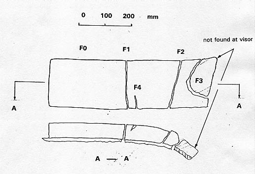
The investigation of fracture F1 - F4 ascertained that all the transverse fracture had started and penetrated from the outside by corrosion assisted fatigue cracking. In addition, fractures F2 and F3 reveal major bending displacements of their flanks, in particular fracture F3 reveals a specific bending angle of about 70° combined with severe bending deformation following the original crack development.
(2) The Atlantic
lock
The inspection
of the original lug remains recovered from the wreck of the ESTONIA at KTH,
Stockholm revealed that the failure of the Atlantic lock took place by rupture
of the 3 lugs welded to the forepeak deck of the ferry, viz. at first to their
circular welds to the housing/bushing, subsequently in the remaining cross
sections by overload shear at about 40° to the mounting plane on forepeak
deck, whereby also bending distortion prior to final cracking of the assembly
was found.
The visor mating
lug was found to be deformed by bending of about 15°-20° to starboard whereby
apparently a crack had opened in the weld between the visor bottom plating
and a vertical support stiffener.
The bore of
this mating lug had an original diameter of 85 mm, however, which was measured
to be 91 x 105 mm with an oval deformation towards forward indicating the
main force direction to have been aft.
Note: This is a confirmation of the structural analysis of the visor by the FE method - see Enclosure 34.2.430 - according to which the force direction at the Atlantic lock was found to be aft as long as the visor hinges were intact.
Another downward bending movement of about 8°-10° was found which indicated forward tilting of the visor bottom prior to the failure of the lock.
Note: This is only possible if the hinges had failed already.
It was further found
that the position and shape of the visor's mating lug did not fully comply
with the available drawings, thus changes had been made during the life of
the vessel.
Further examinations
revealed that about 90% of the length of welds between the lugs on the forepeak
deck and the bushing/housing had been pre-cracked by fatigue. The crack propagation
together with the corrosion showed a similar picture as found on the visor
stempost.
In summary
of the above it can be concluded that the welding seams between the lugs on
the forepeak deck and the bushing/housing as well as the welding seams between
when the visor lug and the visor bottom have been considerable pre-cracked
by fatigue.
Deformation
indicate a sideways and downwards movement of the visor during final failure
of the Atlantic lock.
(3) The side
locks
The starboard
lug has been torn off the visor bulkhead in such a way that the crack started
at the upper edge of the weld between the lug and the visor plating, then
propagation in a downward direction, being inclined to starboard by about
20° against the vertical, leaving a steel tongue at an angle of more than
90° to the bulkhead surface before final separation of the lug from the visor
plating.
The port lug
location indicates a more vertical down tearing movement during crack propagation
without leaving a steel tongue before failure. No detailed investigation of
the character of the fractures have been performed nor were the welding seam
remains examined.
(4) Actuator
mountings on B-deck
The starboard
actuator was torn off from the supporting B-deck structure, whereby the welds
failed first and the vertical stiffeners below the B-deck plating subsequently,
leaving strongly deformed steel tongues behind. Inspection of the dismounted
port actuator revealed a repair weld in way of the vertical stiffener at a
location with possible high stress during the opening procedure. Investigation
revealed the fatigue cracked area to cover 50-70% of the total load-carrying
area of this weld.
(5) Actuator
hinges at the visor arms
At a distance of 1300 mm forward of the visor's main hinges the actuator hinges
(fastening) were fitted underneath the visor arms and permitted the actuators'
sideways movements up to an angle of 15°. No specific structural failures
could be found by visual inspection. Severe scratch marks were found with
complete removal of the paint at an angle of 8-10° against the horizontal.
At the linear forward edges of the lug plates deeper surface damage had been
caused as compared to the curved aft edges. It can be concluded that these
scratch marks are a result of the cutting process of the lug plates through
the forecastle deck plating. The scratch mark inclination of 8°-10° against
the visor arm would coincide with a forward rotation of the visor around the
Atlantic lock while the lug plates were cutting through the deck structure
and the side locks had failed already.
(6) The visor
hinges
The visor's hinge system design consisted of the starboard and port side hinge
arms fabricated from structural platings, with two attached lug plates on
each side, carrying support bushings with bronze liners in the respective
bore holes. The support bushings were welded to the lug plates with circular
fillet welds. The visor hinge lugs were mated by deck hinge fittings, represented
by lugs welded to the forecastle deck. The mechanical connection was one bolt
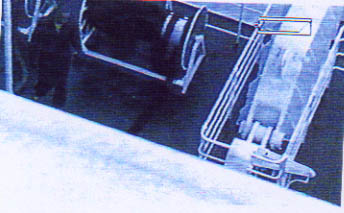
on each side. The video image below shows the starboard hinge arm shortly
be- fore the accident.
The following picture shows the broken port visor lug plates with the frac-tures A1, A2, A5 and A6.
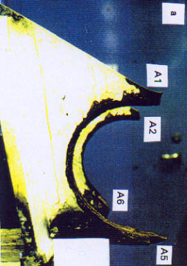
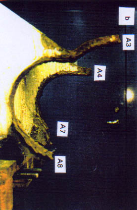
The outer port side shows a vertical to slightly horizontal bending to port side at the fracture at the lower part of the remaining bore. The inner port side lug and both starboard lugs - see picture below - did not exhibit significant bending deformations. The picture below shows the broken starboard visor lug plates with fractures A3, A4, A7, A8:
The failure of the
visor hinges occurred by fractures A1-A8 of the visor lug plates together
with the fillet welds to the support bushings. The bolts had been ripped out
of the hinges, together with the bushings.
The four visor
lug plates revealed various amounts of macroscopic deformation and necking
at the fracture locations.
The fractures
A1-A4 of the upper locations of the remaining bores were indicating considerable
less necking as compared to the lower fractures A5-A8. In particular, the
upper fractures A3,A4 of the starboard lugs exhibited only very small fracture
edge contractions, yielding substantially identical cross sections of the
fractures and the plates as taken from the design drawing. Fracture A4, shows
delaminations originating from longitudinally to rolling direction orientated
inclusions.
The respective
upper fractures of the port side lugs A1, A2 showed visible necking with some
reduction of local cross sections. the lower fracture of the outer port side
lug A5, was considerable necked representing a typical shear failure.
The lower fractures
A6 of both the inner port side and the outer starboard lug A8 were heavily
deformed by bending and hammering. As a particular feature, the inner starboard
upper fracture A3, was accompanied by numerous secondary cracks. Some of them
even penetrated the lug plate in radial direction without significant macroscopic
deformation.
The visual
investigation of the failed fillet welds between the hinge lugs and the support
bushings revealed different cracking modes at the upper and lower fractures
of the hinge plates. Close to the upper hinge lug plate fractures, A1-A4,
the fillet welds had failed mostly by cracks parallel to either the hinge
or the bushing surface.
The cracks
propagated also very often below the respective base material surfaces. At
the lower fracture areas of the hinge plates A5-A8, the fillet welds seemed
to have failed more by a shear fracture of the weld metal, revealing thicknesses
between 5 and 7 mm. However, there were also hammering effects on the weld
crack surfaces in this area which was more subjected to compression than to
tensile stress.
One bushing
had been recovered from the wreck while the remaining visor hinge lug plates
had been removed from the visor for investigation at the Institut för Hållfasthetslära
of KTH, Stockholm.
The fractures
and cracks of the upper locations A1-A4 of both the starboard and port side
hinge lug plates exhibit ratchet marks and fatigue bench marks which demonstrate
the start of fatigue cracking from flame cutting marks in the inner bore of
the lugs. This applies also to the lower fracture of the inner starboard lug,
A8.
For further
identification of the cracking mechanism, a section was removed from the inner
starboard upper fracture A3 area containing the above mentioned secondary
cracks. As from the metallographic investigation, fig. 46, the cracks developed
stepwise and showed side branching with corrosion products being typical for
corrosion supported cracking.
The investigation
of one of the secondary cracks (A3) revealed numerous smaller secondary cracks
also starting from the inner asymmetrically applied deep flame cuts. The formation
of respective ratchet marks can be clearly demonstrated at the crack initiation
points, which show successive striation marks at various locations of the
secondary cracks being created by stepwise crack propagation in radial direction
of the visor hinges.
The fatigue
cracks of the visor hinge plates did however also initiate from the outer
surface of the hinge plates. The inner bore holes of the hinge plates were
originally drilled by machining, however, the surfaces visible outside of
these areas were noted as having been destroyed by inadequate application
of flame cutting.
The fracture
of the recovered hinge bushing was fitting to the fracture of the inner starboard
hinge lug. It exhibits a gap of about 4-6 mm between lug bore and support
bushing. This gap is almost entirely filled with corrosion products, presumably
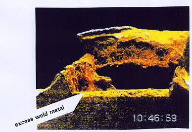
magnetite, which is also found in thick layers at a location where both hinge
late and fillet weld failure are represented together with some excess weld
metal, see arrow on the picture below which may have provided a local notch
effect.
In another cross
section, also severe corrosion inside the gap is identified and the surface
of the hinge bore and the bushing exhibit a considerable misalignment, which,
during welding of the left fillet weld, was overcome by a buffering layer.
The misalignment corresponds to asymmetric burning marks, for example of the
inner starboard hinge.
For closer
investigation only a small part of an adhering fillet weld of the support
bushing was available. It included both a full crack of the hinge plate material
and a secondary crack close to the weld metal and showed also the flame cut
surface of the hinge plate bore hole. While the full crack revealed plastic
shear at its flanks, the secondary crack had started from the heat affected
flame cut surface and propagated close to the heat affected zone of the weld
in radial direction.
Based on the
evidence provided by the above investigation, the following conclusions can
be drawn:
- The fillet welds between the hinge plates and the bushings seem to have partially failed a considerable time before the casualty due to corrosion supported fatigue.
- The partial failure of these fillet welds provided access of seawater to the gap between the hinge plates and the bushings and caused reduction of load carrying capacity of the hinges.
- Both effects facilitated the start and propagation of extensive corrosion fatigue cracking of the hinge plates at another location which occurred also a considerable time before the casualty as demonstrated by the corroded appearance of the fracture of the inner starboard hinge.
- It has to be assumed that the inner starboard hinge may have failed first with only a small macroscopic plastic deformation at the edges of the fracture and without leaving bending of the rest of the hinge plate.
- As the port inner hinge plate was found to be bent to port and plastic necking at the fracture was noted, it has to be assumed that the port hinges failed after the starboard hinges.
The above explained
investigation of the various parts of the ESTONIA visor system has provided
sufficient evidence that the visor hinges, in particular, the starboard hinge
lugs, were severely precracked, before the casualty. There is also evidence
that the fillet welds between the visor hinge lugs and the support bushings
failed due to corrosion assisted fatigue.
In order to
determine the required strength assessments, a Finite Element Calculation
of the stresses in the above welds was carried out which considered four different
directions of loads on the hinge lugs and established the location of the
maximum fracture inducing radial stresses in the fillet welds for each direction
and for various applied loads. The thickness of the fillet welds were taken
as 7 mm.
For example,
the normal visor opening procedure created a vertical down force of maximum
375 kN on each hinge lug based on nominal visor weight and respective leverages
and resulted in maximum radial stress in the fillet weld found at the location
as marked by the circle in the drawing below together with the stress distribution
in radial direction. Accordingly the opening procedure would thus create a
local radial weld joint stress of 75 N/mm².
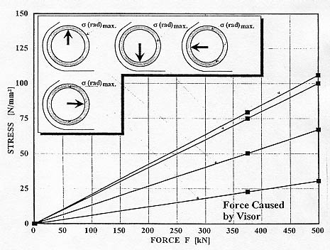
It is thus obvious
that, during opening of the visor, the location of maximum radial fillet weld
stress is found in the same region where fatigue cracking of those fillet
welds initiated. However, also the other assumed directions of loads on the
visor hinges would provide maximum radial stress locations. In particular,
a similar stress range as for the opening procedure would result from an assumed
aftwards force on the hinges. Such an aftwards load could have created the
conditions for crack initiation and failure of the hinge plates, following
the failure of the fillet.
From the present
investigation the following conclusions are drawn:
- The ESTONIA bow visor system contained considerable amounts of fatigue cracking which was created by dynamic loads during normal service. The visor hinges showed the largest amount of pre-damage, together with the mountings of the hydraulic actuators.
- The failure of the bow visor hinges was initiated by failure of the fillet welds which were vital supporting joints between the visor hinge plates and the supporting bushings.
- The failure of the hinge fillet welds at locations of high stress was initiated by corrosion fatigue a considerable time before the casualty.
- The dynamically loaded hinge plates failed by fatigue cracking and subsequent plastic overloading of the remaining weakened cross sections. The fatigue crack initiation at the hinge plates was favourised by corrosion, reduced load-carrying capacity and burning marks.
- In addition to the visor hinges and the actuator mountings, there were various other pre-damaged locations, in particular, the stempost and the bottom lock area, which may have contributed to overloading of the hinge locations.
The complete Report is attached as Enclosure 30.417.
![]()