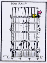
29.2 The Bow Area
part
2
The following damage description and evaluation is based on the video footage made by the ROVs and divers as described in the previous Chapters 25, 27 and 28.
In detail:
(1) - The locking devices

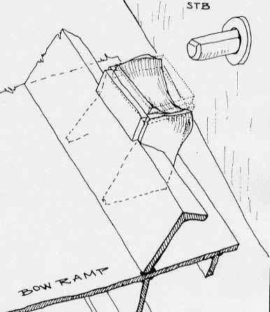
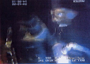
No. 1.1.1 - The picture below shows the mating lug for the starboard ramp hook severely twisted to starboard and downwards (looking from the ramp in normal condition), but the bolt apparently intact.

On the video footage available to this 'Group of Experts' the starboard ramp hook is not visible in full length, it is, however, accessible and the diver has been very close! It would be very surprising if this hook as well as the port one had not been inspected during the first diving inspection, when the first diver lost his wristwatch in the bow ramp which was found during the second inspection by diver 2. The video for the second inspection is available, however, not for the first one.
No. 1.1.2 - The picture shows the area of the port mating lug for the ramp hook, which is evidently intact with the bolt not affected. Since also the ramp hook was neither stretched nor broken - see page 778 - it had not been engaged before the casualty.

The next picture shows the intact ramp hook. The diver - when seeing it - said: "There is a latching mechanism" pointing to it (see his hand on the picture).

No. 1.2.1 - The upper mating pocket on starboard side with the top plate completely missing. There are two possibilities:
(a) The top plate
was completely torn off by the fully extended bolt, or
(b) the top
plate was not in place, because it had been cut off by crew members in the
morning of 27 September 1994 after arrival in Tallinn as witnessed and reported
by a truck driver.

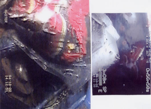
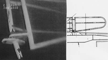
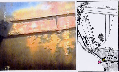
No. 1.2.2 - The lower mating pocket on starboard side is crushed, i.e. the top plate and the longitudinal side plate were pushed in, the upper and lower side plates were still in position, but bent inwards. The damage picture is actually opposite to what it should be if the bold would have engaged an intact pocket and the bow ramp would have been forced open. Then the top plate would have been pushed by the bolt from inside to the outside and probably broken.

Unfortunately the video quality is extremely poor because when the diver saw the pushed in condition of the pocket he started to rub it with his glove and the picture became totally foggy as can be seen. Nevertheless, the contours of the mating box are visible and are made more clear by the drawing next to the image below.
The diver started
to explain this unusual and unexpected damage in this location, but was stopped
by the supervisor who said: "They are just interested whether the bolt
is fully extended." The diver, turning away from the crushed pocket: "The
bolt is fully extended."
The only
possibility of such damage being caused in such a location was by closing
the ramp by force when the bolt was already extended. Therefore, it has been
assumed that the bolt had been extended when the ramp was closed some time
before the casualty and the top plate and the adjacent longitudinal plate
were pushed in, as visible. Never since this occurrence was it possible to
close and lock the ramp properly.
No. 1.2.3 - The port upper mating pocket was found to be intact and undamag-ed, just the metal of the side plates was slightly cracked according to the diver. There are two pictures available showing the pocket and the extended bolt (according to the diver fully extended) which can be seen below.

Both pictures clearly indicate the misalignment between bolt and pocket which is - according to the diver - about 4 inches or 100 mm, i.e. the pockets were about 100 mm above the bolts (when the vessel was in upright condition).
No. 1.2.4 - The port lower mating pocket was completely undamaged. The diver found a rope turned around the pocket which had obviously been done by somebody prior to the sinking. The rope runs up between ramp/bulkhead where it is jammed in and still visible on the 1996 video tape.

The same misalignment between pocket and bolt as observed already at the upper pocket/bolt is apparent from the picture below, which also shows that the securing bolt was only slightly extended - about 1 inch = 25 mm according to the diver - and that some rags were hanging out of the opening next to the bolt.

No. 1.3 - Lifting eye pads respectively the attachments for the ramp actuators are no more existing on both sides. This will be explained when the ramp actuators are discussed.
No. 1.4 - The starboard lug for the preventer wire is completely undamaged and intact. (See following image.)

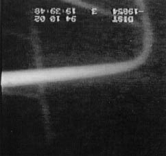
The preventer wire which should have been attached to this lug by shackle is hanging in full length up and down with the shackle still attached to the lug of the lower end - see the two pictures below from the ROV inspection on 09.10.94.

The apparently unbroken bolt is still attached to the shackle. - See also Chapter 27 - pages 722 ff.
No. 1.4 - The lug for the port preventer wire at the bow ramp is unbroken and intact - see the right image. The port preventer wire is still shakled to the lug at the port side of the car deck opening - see left image - but cannot be followed the full length on the available video footage, thus it is not possible to ascertain whether the wire is broken or not.

(2) The actuators
The attachment
points in side view are shown on part of drawing 49111-387 below with the
ramp in closed condition.
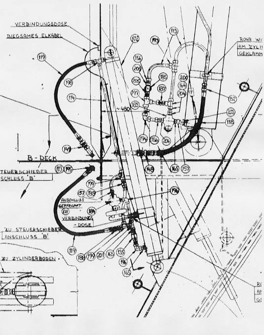
The left drawing shows the cross-section of the retracted actuator with both attachment points. The lower one consisted of two lugs welded to the landing extending over the side of the ramp as can be seen from the drawings below.

The lower end of the piston rod was mating between the two lugs con-nected by a strong bolt to the ramp. The landings at both sides were of rather strong construction similar to those for the two mating lugs for the ramp hooks. The drawing on the next page shows the ferry with open visor and closed bow ramp. The two landings on each side extending the ramp sides are clearly visible (see arrows).

The picture below shows the port actuator extending out of its opening in the recess of the front bulkhead.
The port actuator
and its fastening.
Due to the ramp being pressed to starboard the port recess of the front bulkhead
is visible with the opening of the actuator.
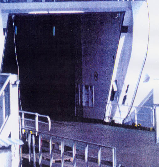
The following images of 02.10.94 show the area of interest with the
ramp in the foreground, the extended landing for the fastening of the actuator
to the right, 3 Teco lines rising up and the openings for the hydraulic and
manual lock in the front bulkhead. The recess with the opening for the actuator
and the actuator are not visible. The ramp appears to be more or less in normal
closed condition.

The next image made from the video taken on 09.10.94 shows the gap between ramp and the longitudinal part of the recess to be much wider, i.e. the ramp was now shifted more to starboard compared to the situation on 02.10.94.

The following image from the same video also shows changed rope positions and a box attached to the longitudinal part of the recess of the front bulkhead directly above the opening with the ramp actuator fastening (when the ramp was in closed condition). This box is visible on the videos made on 02.10.99 only as a shadow but apparently it was there already. The reason for this difficulty is the much smaller gap between bulkhead and bow ramp at that time. The box will be explained further in Chapter 32.

Not only did the
gap increase between 02. and 09.10.94, but also more Teco lines (floatable
mooring lines) were rising up between ramp and bulkhead. One of them appears
to be turned around the box which must have been manmade. This is surprising
because at that time "officially" no divers had been down to the wreck.
The next available images are made from the ROV and diver videos of 01.
to 04.12.94 and show the same area, however, again with remarkable changes.

The box and all
the hawsers but one have disappeared, the gap appears to be wider.
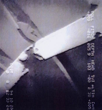
Close ups made from the diver videos of the one hawser left proved it to be
jammed in between the extended landing for the actuator fastenings and the
bulkhead - see the image below. To the left is the ramp landing and to the
right the bulkhead. It is obvious that such jamming can only occur when the
ramp was moved open/closed which must have been the case between 09.10.94
and 02.-04.12.94.

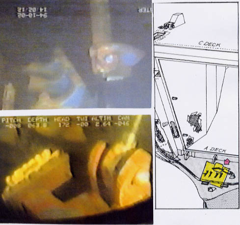
The following images - also made from the diver video B40c - show the lower part of the opening for the actuator with the actuator inside and above the lower part of the landing for the fastenings of the actuator extending the side of the bow ramp. Underneath this landing the rather massive construction of the fastenings of the actuators should be visible, but there is obviously nothing.

The actuator can be seen on the following image inside the opening in slightly extended condition with the lug at the bottom end of the piston rod broken. The slight extension of the actuator corresponds to a ramp opening of some 10-15 cm at the top.

The following image shows the complete lower part of the opening looking from upside down (in normal condition). The actuator with the broken lug of the piston rod (bright spot) is visible and - behind the actuator - in almost upright condition some object which upon a very detailed video evaluation turned out to be an angle iron. The two dark areas in the white paint of the bulkhead proved to be two deep indentations obviously caused by the angle iron under pressure.

The enhancement of the image showing the affected area reveals two deeply pressed in parts at the edge of the opening with an unaffected part in between.

As stated before in Chapter 27 it has to be assumed that the crew fitted the angle iron in place to support the closing operation, i.e. to ensure smooth closing of the port side of the ramp which was detached from the vessel due to the broken hinges and which was considerably pressed down during opening and closing of the ramp.
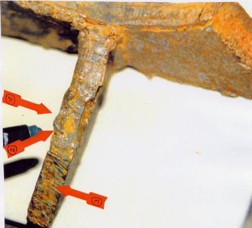
The starboard actuator area looks totally different compared to the port one because there is very heavy damage, the probable cause of which shall be explained in Chapter 32. Among other things also the fastening of the starboard actuator to the bow ramp was affected. All available images from this part of the ramp are made from the ROV video of 09.10.94, thus show the ramp pressed against the starboard longitudinal bulkhead part of the recess. For orientation purposes the first image below shows the transverse girder at the bottom in the middle which runs up diagonally to the left where a large crack is visible. The strong girder running from left middle to right up is the starboard outside longitudinal girder. At the port side of the mentioned transverse the landing for the fastenings of the port actuator were fitted, at its starboard side the fastenings for the starboard actuator were fitted.

The next image shows the underside of the burst open landing. At the left side of the picture the longitudinal part of the recess is visible with the extended opening for the manual side lock.

The next image is a close-up looking slightly more from below (in normal condition) which clearly shows the full extent of damage to the burst open landing. The landing was pushed upwards and the steel structure burst open. Behind the two triangle-shaped brackets below the damage the broken piston rod is visibly jammed in (see arrow). It broke in the lug at the bottom end of the piston rod approximately in the same way as the bottom end of the piston rod of the port actuator had broken.

A further close up of the very small gap between the ramp (below) and the recess respectively front bulkhead (above) shows deep scoring marks indicating an opening movement of the ramp and - obviously - closing thereafter as assumed already from the indications at the port side.

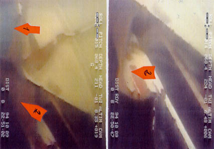
The following image shows the area of the damaged landing at the right top side and then to the left edge of the ramp with the recess and a piece of the front bulkhead behind respectively above, but the strong outside girder very severely bent to the inside of the ramp with both ends cracked off the transverse girders.

The bottom (right) side of the girder was attached to the lowest transverse girder of the bow ramp to which at the bottom side of the hinges are fitted. For clarification purposes the important details on this image have been numbered as follows:
1. broken and jammed piston rod of actuator
2. burst open landing
3. front bulkhead
4. outside edge of bow ramp
5. triangle bracket of landing
6. upper side of cracked off girder
7. lower side of cracked off girder
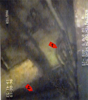
As the ramp mainly covers the opening for the actuator only a small part of the lower area is visible together with the broken part of the piston rod with the lug of the actuator as can be seen from the image below made from the diver video.

The dark area at the top (arrow 1) is the opening for the actuator, the broken part of the piston rod can be seen at the right below the big bright spot (arrow 2). The bent steel to the right are parts of the landing blown open (arrow 3). As it is quite obvious that the broken piston rod is some distance away from the opening, it must have been broken twice, viz. first in the lug of the piston rod the same way as on the port side and subsequently, and again when the ramp was forced into closed condition, after the 02.10.94. The following image was made from the same video tape B40c when the diver was looking between ramp and bulkhead. It shows the lower part of the opening for the ramp actuator with the steel at the edges bent from inside to outside and partly cracked.

The images show that the lower part of the starboard front bulkhead - below the opening for the manual side lock - was cracked at various locations and apparently torn off the forepeak deck. It could not be deformed outwards, i.e. forward because the visor was there, thus the pressure escaped to both sides, which cracked open. On the starboard side there was just water, but on the port (inside) there was the ramp and the result is visible by
(a) the extremely bent and distorted lower part of the outer vertical girder being cracked off upside and downside from the respective transverse girders to an effect which cannot be explained by mechanical impact, and
(c) the burst open and severely distorted landing to which at the lower side (looking from the then position of the ramp) the fastening of the ramp actuator had been located.
(3) The hinges were found damaged to varying extent.
The port outer
hinge was already damaged a long time before the casualty, actually to
a certain extent already when the vessel was taken over by N&T from Wasa Line.
See Subchapter 6.5. The then already existing damage deteriorated with each
opening/closing. Due to the misaligned ramp the bolt of the hinge apparently
turned itself further and further to starboard out of the bearing, the securing
plate broke and finally the outer lug slipped off the bolt and the inner one
broke either simultaneously or subsequently. The port side of the ramp was
detached from the vessel for a considerable time before the casualty.
The following
image taken from the 02.10.94 ROV video shows the totally misaligned bolt
much too far to starboard leading through the bearing bushing inside the strong
lug fitted to the forepeak deck. At the bottom of the picture in the middle
is the undamaged complete outer lug of the ramp visible and on the right side
the upper part of the broken inner one.

The following image taken more from the starboard side shows the bolt far extended to starboard with two steel pieces underneath. In the left lower corner the broken inner lug of the ramp can be seen.

arrow 1 = steel pieces
arrow 2 = bolt
arrow 3 = broken inner lug
The drawing below explains the damage condition of the port outer ramp hinge.

The following image
taken from the 02.10.94 video shows the location of the port outer hinge with
slipped off, intact outer lug some distance away from its original position
because evidently a gap had opened and the ramp became detached from the vessel
in this area and through this gap between forepeak deck and bottom of ramp
water could freely penetrate on to the car deck from the visor which was always
water-filled at sea.
This gap was
plugged by mattresses - see the blue transverse one above the hinge remains
- the vertical plastic sheet to the right of the blue mattresses, the red/white
bedding next to the plastic sheeting. The videos from 02. and 09.10.94 are
showing blankets and rags further up in the gap between ramp and bulkhead.
Also the following image shows the same area, but slightly further to starboard. The rubbing marks on the bedding indicate that it had been in place during several openings/closings of the bow ramp.
In December 1994, when the divers came this "sealing material" was gone with exception of one red piece of bedding or the like apparently sticking in a hole in the damage area of the lower part of the port front bulkhead as can be seen on the following image also from the 02.10.94 video. The area in question is between the ramp at the left and the pipe with the hydraulic line for the Atlantic lock at the right.

The following image originates from a video made during an ROV inspection of the wreck on 19.06.96, i.e. 11/2 years later. The ROV also had a look at exactly the same area which is shown by the previous image, however, next to the hydraulic pipe to the Atlantic lock there is now a strong lug visible welded to the bulkhead which could not be seen on the previously made videos due to the presence of the "sealing material". According to the yard the wire steering of the upper bow ramp flaps had been fastened to this lug (arrow 1).
Arrow 2 points to some damage in the bulkhead which was previously also not visible due to the "sealing material".

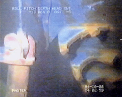
The port inner hinge was also broken prior to the casualty, probably shortly or immediately after the outer hinge had become detached from the vessel. The image below shows the broken parts.

The inner starboard hinge was found to be intact by the diver with the lugs elongated. See the images below.

The outer starboard hinge was found to be intact but also elongated according to the diver. The following two images show the condition from inside and outside.

In summary the pictures/images/drawings shown and explained on the previous pages 847-855 demonstrate the following condition of the bow ramp hinges:
- Each hinge consisted of two lugs - one inner, one outer lug - connected to the ramp, one lug connected to the vessel, one hinge bolt and one bearing/bushing. The bolt was secured by one plate at each side which were bolted to the bushing.
- Evidently the bolt
of the port outer hinge had moved inside the bearing/bushing and had broken
the securing plates which were missing at both sides. The reader is reminded
that already the last Finnish crew had demanded the renewal of this hinge.
See also Subchapter 3.4 and 6.5.1.
Apparently
due to the misaligned ramp the bolt worked itself to starboard until the outer
lug shipped off the bolt, which apparently caused the inner lug to fail. See
right the drawing below (PS outside).

The additional load caused also the port inner hinge - see the left drawing (PS inside) above - to fail after some time leaving the bow ramp detached from the vessel at the entire port side.
- The detachment of the complete port side of the ramp from the vessel resulted in
(a) an increasing misalignment of the whole ramp, and
(b) an increasing gap between the ramp and the ramp opening of the car deck.
- Furthermore the bow ramp in its function as part of the upper extension of the collision bulkhead above bulkhead deck was no more weathertight, i.e. the car deck was open to the sea as the visor was always quickly water-filled at sea.
- The gap between bow ramp and car deck ramp opening at the port lower corner extended from the corner to the centre line and upwards to about B-deck level.
- In way of this gap mattresses, plastic sheets, plastic covered bedding, blankets and rags were found, obviously serving as "sealing material".
- As a result of the port ramp side being detached from the vessel there was also a vertical misalignment between the port ramp side and the adjacent plating of the car deck opening, i.e. the mating lug for the ramp hook and the mating pockets for the securing bolts extending from the adjacent plating were about 100 mm higher up now and could no more be reached by the hook respectively by the bolts already for some time before the casualty, i.e. the port side of the bow ramp could not be secured at all for some time before the casualty.
- It follows that the entire port side of the bow ramp was not locked/secured upon departure from Tallinn on 27.09.94.
- The starboard inner hinge was still intact, but the ramp lugs were subsequently elongated, i.e. worn, and they would have been the next ones to fail.
- Also the strong outer starboard hinge showed signs of wear and elongation and hence had lost its initial load-carrying capacity.
- This means that at the time of the casualty the bow ramp was merely connected to the vessel by the weaker inner and the stronger outer starboard hinges, both of which, however, were substantially worn and hence their load-carrying capacity was reduced correspondingly.
(4) Damage to the construction - (See drawing page 869)
The inside of the bow ramp is only briefly visible when the diver climbs up the starboard side to the flaps at car deck level, pulls himself up along these flaps to the port side hinges and further to the lower securing bolt with mating pocket. On the ramp plating there are two areas with burnt and/or damaged paint, i.e.:
- There is an area of ca. 1 m² located between the upper flaps and the level of the car deck opening where the paint is burnt and the plating is severely distorted. The area is inside the ramp house when the ramp is closed.
- The lower area is located in the 3rd row of steel profiles, looking from starboard, which are welded to the ramp plating and the 6th or 7th profile from car deck level as indicated on the picture below by the dark spot. The paint of the plating as well as the two flaps below looks reddish/brown. The plating otherwise does not look affected, but the two flaps are bent and distorted and the car deck plating in way appears to be affected.
Otherwise the ramp plating appears to be intact as far as visible. The rails are completely missing on both sides. - See Subchapter 27.6 and further below in this chapter.
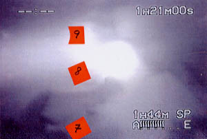
The flaps on the lower side of the ramp normally covering the gap between car deck and ramp were found to be as follows (from starboard to port):
- the flap Nos.
1 and 2 were green and intact and upright;
- No. 3 looked
brownish/red, was also upright with the upper edge bent;
- No. 4 looked
intact, brownish/red and upright;
- No. 5 was
green, upright and intact;
- Nos. 6/7
was bent towards the car deck and looked brownish/red;
- Nos. 8/9
looked new and green, were upright and undamaged except for a bent edge of
the No. 8.
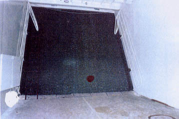
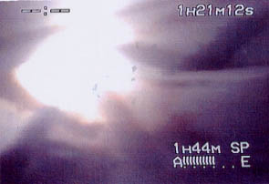
Through the gap between the last flap and the car deck, something big and red, probably bedding in plastic, is visible which is sticking in a big hole in the longitudinal car deck bulkhead. See the following image and drawing:

Note: The
drawing does not show the bow ramp with bottom flaps.
This part of
the damage will be explained in detail in Chapter 32.
- Otherwise the raised edge along the starboard side of the ramp (tire-protection bar) with rail, lug for preventer wire and welded pocket for securing bolts, was noted to be torn off of the girders in way at the forward end as visible from the image below (see arrow).

- The corresponding raised edge along the port side of the ramp is not detached from the ramp anywhere, but buckled and smashed at its forward part as well as the complete forward part of the ramp including the bell crank for the flaps. It was noted when the diver moved down (up) along the port side of the ramp from the port lower pocket of the securing bolt to the upper side that the upper part of the raised edge (tire-protection bar) with lug for the preventer wire and upper pocket for the securing bolt were bent towards the inside, i.e. centre line, of the ramp. This bending under force is presumably the cause for the cracked metal between the upper pocket and ramp edge as explained further above under "locking devices".
- The lugs for both preventer wires are completely intact and undamaged and the conditions of the four pockets for the securing bolts have already been explained under "locking devices" further forward in this chapter.
- The upper flaps were found to be in the following positions on the first (known) ROV inspection on 02.10.94:
- From starboard to port Nos. 1 - 4 were hanging upside down and the lower parts moved to the deep starboard side partly over-lapping each other with no apparent damage;
- Nos. 5 and 6 were obviously forced apart and were now standing approximately horizontally with damage in between;
- Nos. 7 and 8 were hanging down in undamaged condition with the lower parts slightly moved to port.
The bell crank on port side was bent and broken with the wire controlling the flaps also broken. The starboard side bell crank is apparently intact.
Behind the first and fourth flap port side a rope is visible.
Between the upper transverse girder of the ramp and the second flap from starboard a wooden plank was found to be sticking.
- The mating lugs for the ramp hooks and its fastenings have already been explained under "locking devices" and the fastening landings of the ramp actuators have been explained under "ramp actuators" further forward in this chapter.
- The port outer ramp edge between the flap hinges and the raised edge was found to be buckled, deformed and bent.
- The corresponding part on starboard side was apparently undamaged with exception of about 1/2 m forward of the raised edge (tire-protection bar) which was apparently "tied in". The same bending due to "tightening in" was noted on the corresponding port side of the ramp.
Otherwise there is no more apparent damage to the inside of the bow ramp.
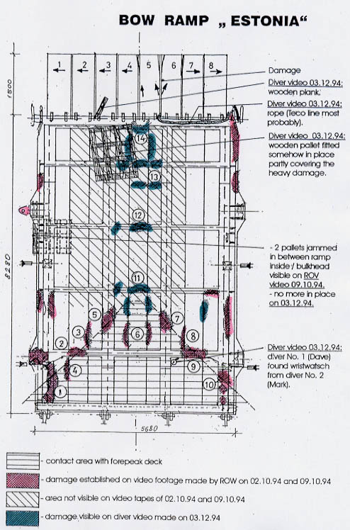
The outside of the bow ramp was found to be damaged very substantially and the damaged areas, according to the ROV inspections on 02. and 09.10.94 compared to the results of the diving investigation on 03.12.94, are demon-strated by the drawing on the following page. It has to be borne in mind that the green shaded area containing the really heavy damage at the centre line of the transverse girders Nos. 3, 4, 5 as counted from the lower side of the ramp is not visible on the videos made on 02. and 09.10.94. This does not mean that it had not been there, but this particular area cannot be seen on the publicly available video footage, because these parts were cut and deleted from the respective videos handed over to this 'Group of Experts' by the members of the Finnish Commission in March 1995 as "raw material". - See Subchapter 34.6.
In detail:
The red shaded
area represents the contours of the forepeak deck and it is obvious that the
damage to the 2nd transverse girder as well as to the two inner vertical girders
appears to have been caused by contact with the corresponding parts of the
forepeak deck. Also the type of the deep and sharp indentations of the transverse
and vertical girders, with local deformations to the adjacent structure, could
confirm this. On the other hand the damage to the port vertical girder is
comparatively weak, while the most heavy damage to the starboard vertical
girder cannot have been caused by contact with the forepeak deck because the
two ramp hinges on that side were to some extent intact. The doubts are further
increased by the fact that the flatbar housings on the forepeak deck at the
four contact areas should be pressed flat, which they were not, and that there
should at least be heavy contact marks at the deck edges of the forepeak deck,
which however are also missing.

To allow the reader to form his own opinion the relevant damages shall be shown on photos and explained below.
In detail:
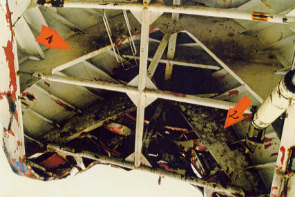
(a)
ROV inspection 02.10.94
The two images below show on the left side the starboard lower port side with the outer vertical girder cracked off the bottom transverse girder, the ramp plating and the 2nd transverse girder and which is twisted by about 70° - No. 1 on drawing. The image on the right side shows the correspond-ing port girder with some scorings only and damage further up.
The dramatic damage to the starboard girder cannot have been caused by contact with the forepeak deck, because if the ramp would have smashed onto this deck also the port side should have been damaged. Also the nature and extent of this damage to the starboard girder does exclude that the damage was caused by impact on the forecastle deck.
The following image shows the port inner vertical girder - arrow 1 - and the 2nd transverse girder - arrow. 2. The damage on the left is No. 9 on the drawing, the bent profile next to it is No. 8, the dark spot in the right lower corner is No. 7 and the two profiles bent to the outsides are No. 6 on the drawing.
During the ROV inspection on 09.10.94 a better quality footage was produced and the images below show the area of relevance in much more detail.
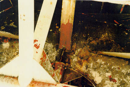
The three images below show the damages Nos. 2, 3, 5 on the drawing.

Obviously the transverse girder No. 2 between the outer and inner vertical girders on port side has been pushed upwards - damages Nos. 2 and 3 - which cannot have been caused by an up-and-down movement of the ramp and respective contact with the forepeak deck.
Also damage No. 5 is dubious because the area has obviously been damaged twice, viz.
(1) at first horizontally (the black looking area) and
(2) secondly diagonally.
which cannot have been caused in one occurrence.
The left picture shows the lower part of the port outer vertical girder, cracked off above and below and twisted up to 70° - damage No. 1 on the drawing as well as damage No. 4. The right picture shows damages Nos. 2, 3, 4.
Below is an enlargement of damage No. 2.
(b) ROV inspection 09.10.94
The available footage of 09.10.94 showing the lower port part of the ramp is no better than that of 02.10.94 with the exception of the damage to the lower part of the outer vertical girder. The left picture shows the damage - No.10 on the drawing - to be just below the 2nd transverse girder. The above visible extension to port is the landing for the fastenings of the port ramp actuator. There are two different indentations - arrow 1 and 2 - both run horizontally, thus cannot have been caused by contact with the forepeak deck. The right image is an enlargement of the damage area.

The damages 7 and 9 cannot be discussed because there is no appropriate footage available.
Had the ramp been
smashing onto the forepeak deck the flatbars forming the housing of the rubber
packings on the port side and starboard side of the Atlantic lock installation
should have been pressed flat had the ramp sustained the damages 2 - 9 due
to contact with the forepeak deck, which they are not, as can be seen from
the following images. It has to be concluded that the damages 2 - 9 cannot
have been sustained as a result of contact between the open ramp and the forepeak
deck.
The image
below shows the empty housing for the rubber packings to starboard of the
starboard lug of the Atlantic lock.

The following two images show the area to port and in front of the hydraulic cylinder of the Atlantic lock.

The diving investigation on 03.12.94 revealed very heavy additional damage to the ramp as can be seen from the drawing on page 869. The newly found damages are numbered 11 - 14 and are all in the centre line of the ramp in way of the 3rd, 4th and 5th transverse girders counting from the hinges. The upper transverse girder to which the flaps were fitted was apparently also affected. It is unknown whether these damages - mainly in the centre line of the ramp - were already in existence at the time of the ROV inspections on 02. and 09.10.94 and thus would have to be assumed related to the casualty.
In detail:
- No. 11
The images below show the very severe indentation and deformation of the 3rd
transverse girder with the adjacent structure buckled and the upside of the
girder twisted. The force direction was upwards.
- No. 12 concerns the 4th transverse girder which was apparently pushed in with the structure below buckled.
- No. 13 is a small damage in the centre line compartment between the 4th and 5th transverse girders running horizontally over two sections and the indentations are from inside to outside.

- No. 14 is by far the largest and heaviest damage which was partly covered by a pallet attached to the ramp - see image below left.
 |
 |
After some difficulties the diver was able to pull off the pallet and the full extent of the damage extending over three sections in way of the 5th transverse girder became visible. The heaviest damage was noted in way of the centre line where the girder was pressed together to the plating which was severely buckled. To port and starboard of this very heavy damage the girder was also indented, but to a lesser extent. Also the two vertical frames between the two inner girders above the damage explained before were noted to be bent to the outside and the uppermost transverse girder, to which the flaps were fitted, was also severely indented in way of the centre line.
The inside of this severely affected area is visibly distorted with the paint burnt over about 1 m². See also further above: The inside of the bow ramp.
The left image below shows the adjacent damage to starboard and the right image to port of the big damage.
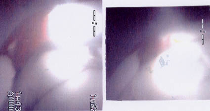
All these images
were produced from diver video B40c which particularly in this part is much
too light and very foggy. This is due to faulty copying of the original videos
to the copies supplied to the 'German Group of Experts'.
The next image
shows the deformations of one of the two vertical section profiles (frames)
between the inner port and starboard vertical girders. The buckling and possibly
pounding damage is extending up to the transverse girder No. 6. The other
section profile looks similar.
The image below,
though of very poor quality, shows the area of damages Nos. 7, 8, 9. The diver
is standing between the port and starboard inner vertical girders next to
the 3rd transverse girder and is looking to port. The respective numbers have
been attached to the corresponding damage.
The enormous
defor-mations, which are not visible to this extent on the videos of 02.10.94
and 09.10.94, indicate that this damage had been created by the twisting of
the ramp when the heavy visor had been hanging on it for some time.
The image below showing damage No. 7 looking from starboard to port confirms the above.
So much for the
main damage to the underside of the ramp, respectively to the severe longitudinal
bending of the whole ramp structure which was most probably caused by a very
heavy weight pressing down the ramp from port to starboard and by which the
very heavy distortions to the vertical and transverse girders of the ramp
structure were created.
This could
explain all the damages to the ramp structure except for Nos. 1, 10 and part
of damages 13/14 to which reference is made in Chapter 32. It is worth mentioning
here that there was no chance for the ramp to crash on the bulbous bow as
long as the starboard ramp hinges were intact, which they were.
(5) The rails
The bow ramp is fitted with two rails on each side as can be seen on the photo
below.
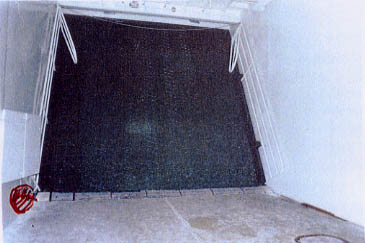
Each rail consisted
of three fixed sections welded to the raised tire-protection bar, i.e. 4 vertical
stanchions with three horizontal rail bars in between. A fifth moveable section
was fitted to the most forward stanchion. When the ramp was open these movable
sections were swung forward and secured in this position by two pins fitting
in corresponding holes. Before the ramp was closed, the movable sections were
swung backwards and secured by the pins as can be seen on the above picture
and the rails remained in this position during the sea voyage. Thus it has
to be assumed that this was also the case during the last voyage.
As parts of
the starboard rail, the 4th section with the attached 5th moveable section,
were found on the seabed already on 02.10.94 by ROV "Jutta II" - see the image
on the next page - the available footage has been evaluated for indications
of the bow ramp rails.
It is obvious that it is the starboard side because the movable part is always fixed at the inside of the fourth section if the ramp is open, as visible here and it is also obvious that the lower, bent part was the part attached to the ramp. It is further apparent that the vertical stanchion had been bent and finally cracked off by a force acting from port to starboard.
The image below shows the aft lower part of the movable fifth section which confirms the before said.
Note: A reconstruction of the track of the ROV which found the rail sections revealed that they are lying ca. 270 m to the South or SSW of the stern of the wreck, i.e. on the initial track of ESTONIA. According to the construction of the casualty sequence-of-events ESTONIA had passed this position at about 00.55/01.00 hours.
The evaluation of the available video footage made on 02.10.94 and 09.10.94 revealed possible parts of the starboard rail in the background - see arrow 1 on the image below - which is however very uncertain.

The image shows the starboard side of the ramp with the side torn upwards and the tire-protection bar obviously still attached to the ramp plating. One rectangular steel part - see arrow 2 - is extending from the opening for the starboard ramp hook. It is unknown where it belongs to and what pushed it out of the opening. - See in this respect also Chapter 32 - Unexplained Damage.
The following image shows the port side of the partly open ramp with the indication of a possible crushed rail - see arrow.

Otherwise there are no further indications of the rails on the footage from 02. and 09.10.94 because the ROVs did not go deeper inside the ramp.
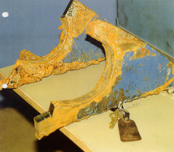
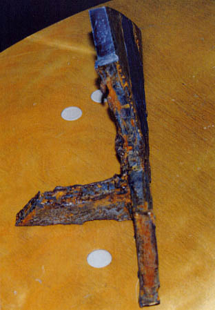
The diving investigation on 03.12.94 revealed that there was nothing left of both rails and that what has to be the 2nd stanchion from forward of the port rail was cleanly cut off at a level well below the adjacent mating pocket of the port upper securing bolt. Bending or cracking can be excluded due to the even surface of the stanchion which was actually a pipe. At the time of cutting the stanchion was bent to the starboard side. See image and drawings below.

The diver walked up (down) the starboard side of the ramp on the bulkhead, where among some pallets and other debris parts of the rail are visible. See the image below.

He later climbed down (up) the port inside of the ramp and only the two mating pockets and the lug for the preventer wire became visible, while the fastenings of the port bow ramp actuator could not be seen, which fact remained uncommented by the diver.
(6) Other observations
Also the
following observations were made during evaluation of the available video
footage:
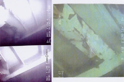
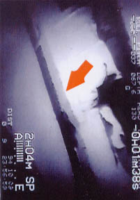
- On the videos of 02.10.94 the ramp appears to be almost closed - the footage is partly brilliant and partly extremely bad. The image below shows the almost closed ramp.

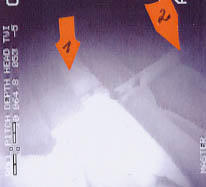
- On the one video tape available of 09/10.10.94 the ramp appears to be more open - see the image below - and deeply engraved scoring marks at the starboard recess in the front bulkhead in way of the fastenings for the starboard ramp actuator indicate that the ramp had been more open and was subsequently closed - see the image on the next page. Since this area is not visible on the footage of 02.10.94, it is not possible to verify whether this opening and subsequent closing occurred in course of the casualty sequence or later.


The arrow points to the scoring marks. The ramp in way of the landing for the starboard ramp actuator is obviously resting on the bulkhead.
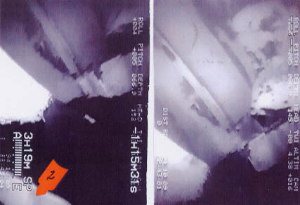
- On the same video
tape from 09/10.10.94 two wooden pallets are visibly jammed between the ramp
and the recess of the starboard front bulkhead just below (above) the starboard
mating lug for the ramp hook. The area is not visible in detail on the 02.10.94
footage, but when the diver inspected the area on 03.12.94 the pallets were
definitely no more in place.
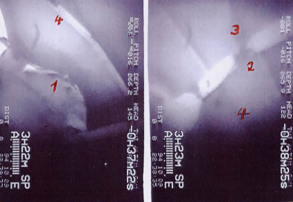
The 2 images
following show the area in question. Arrow 1 on the left image, points to
the landing to which the mating lug for the starboard ramp hook was fastened
and which was apparently pushed upwards - see arrows 2 on both images.
It can be excluded
that these pallets floated into this position at the very moment when the
ramp was pushed closed by the visor while the sinking vessel was already heeling
to 130/140°. It has also to be excluded that the pallets floated out of the
jammed-in condition by themselves as visible on the footage made on 09.10.94.
This means that it has to be assumed that the pallets were manually put into
position to avoid total closure of the ramp at some stage and, further, that
they probably floated away when the ramp was also manually opened further
at sometime after the 09.10.94 but before 03.12.94.
- When diver
1 (David) inspected the outside of the ramp on 03.12.94 he found a running
wristwatch in the lower part of the ramp, i.e. in one compartment above the
broken starboard hinges. It turned out that the watch belonged to diver 2
(Mark) indicating that he must have been there before apparently engaged in
other activities not shown on the available video footage. See the ramp drawing
on page 869.
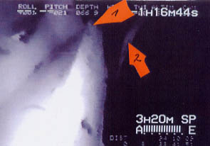
Attention has also to be drawn to the image below from the video made by the ROV Sprint on 03.12.94 - the day when the diver also inspected the bow ramp. The image shows a rope disappearing behind something solid, which is apparently not identical to the "sealing material", which had mostly disappeared by then. The rope can be seen coming back slightly deeper as if running through a lug. This is approximately the area where the lug was found on the 1996 video - see the image on the previous image.

- Definitely neither this rope nor the solid looking object had been in this location during the ROV inspection on 09/10.10.94.
- Next two images made from diver video B40c are presented which show a frogman-type diver swimming into the beam of the diver's searchlight and then hastily withdrawing from it. This diver had no umbilical, thus was completely self-sustained. Diver Dave did not show any reaction.

- Finally it has to be mentioned that a rope was found tied around the flaps Nos. 6, 7, 8 - see ramp drawing and image with drawing below - and a pallet was fitted to the upper part of the ramp - outside in way of the starboard inner vertical - and the 5th transverse girders. Slightly further up the ramp between the 2nd and 3rd flaps from starboard a wooden plank was sticking all of which is indicated on the ramp drawing - see page 888.

The observations mentioned under (6) are reported here for completeness only and reference shall be made in the forthcoming explanations when cross connection might became understandable.

(click for full
page images)
(7) The Forepeak
Deck
The area
under investigation is restricted to the forepeak deck as indicated on the
overview drawing and the detailed drawing on sheet 7. The images 1-6 shall
be explained as follows:
- No. 1 shows the hammered stempost of the wreck
- Nos. 2, 4, 5, 6 show either empty flatbar channels where the rubber packings were supposed to be - which is also confirmed by the image below - or show the rubber packing lying loosely on the flatbars into which they should be fitted and bolted. The evaluation of the video films - of which these 3 pictures are just a small selection - prove that the rubber packings were only in place at the starboard side from forward of the Atlantic lock to the "corner of the mouth" and these were in a rather poor condition. Along the whole port side up into the "corner of the mouth" there were no rubber packings. The diver followed the flatbar - channel for the rubber packings from the top of the starboard front bulkhead via the forepeak deck to the top of the port front bulkhead which is documented on video tape B40c. The two images below are just a confirmation of the findings explained above.

- No. 2 shows the hammered stempost which was evidently not just caused by the contacts with the visor in the course of the casualty sequence, but these quite extensive hammering marks were sustained over a longer period, viz. when the visor moved up and down in the sea state within the play of the locking devices, because the counter-pressure of the missing rubber packings was not existing to avoid such movements. The corresponding stempost of the visor was found to be full of fatigue cracks - see Chapter 30 and Subchapter 34.4.
- No. 3 shows the hammered and bent locating horn (pyramid) which had taken over a weight-carrying function before the casualty for which it was not designed and which was due to the misalignment of the visor. The pre-damaged condition of the pyramid was naturally increased by the heavy contacts with the visor bottom in the course of the casualty sequence-of-events. See Chapter 31.
- No. 2 shows one of the two steel pads welded to the forepeak deck in front of the rubber packings which were fitted to carry about 20% of the visor's weight. The second one has also been identified on the video tapes available.
- No. 3 shows the crushed pyramid, i.e. the locating horn on the forepeak deck supposed to guide the visor in transverse direction during closing.
In addition, the attention of the reader has to be drawn to two circumstances discovered only when the above-mentioned sheet had already been completed, viz.
(a) the lower part of the starboard front bulkhead being torn off the forepeak deck with severe distortions in way, and
(b) the apparent fact that there is no corresponding damage to the flatbar channels of the rubber packings, deck edges, etc. on the forepeak deck, which mandatorily has to be there in case the bow ramp had been fully open and did smash on the forepeak deck.
as to (a):
The lower part of the starboard front bulkhead in way of the hydraulic and manual side locks - see also further forward in this chapter, the starboard front bulkhead - is shown on the following images. The first one shows the upper part of the opening for the manual side lock with the rubber packing to the left. Between opening and rubber packing the bulkhead is visibly bulged - see arrow - i.e. the bulkhead is pushed out around the opening for the manual hook and increasingly deeper down the bulkhead. This can be seen from the next image below - arrow 1. In addition, there is a very deep fold - see arrow 2 - as well as damage in way of the rubber packings - arrow 3.
Apparently the fold occurred between the rubber packing and the outer edge of the front bulk-head and extends down towards the forecastle deck where the front bulkhead was torn off the fore-peak deck plating and its inner side was twisted upwards. See the image below.

On the right image arrow 1 points to the change over from white to blue paint which should actually continue according to the red-dotted line, however, this is not the case due to the considerable distortion of the complete area which was apparently pushed to forward where the visor was at the time.
The following two images show the area adjacent to this pushed-out lower part of the front bulkhead, the recess with the torn-off and severely bent lower part of the outer vertical girder of the bow ramp. Apparently the deck/bulkhead is open in way of these severe distortions which also extends downwards.
The next image looking from upside down shows the lower part of the front bulkhead twisted to port - see arrow 1 - while the initially lowest part of the bulkhead having been welded to the forepeak deck was cracked off and bent to starboard against the deck edge -see arrow 2 on this and the above image.

(click for full
page images)
(8) The Atlantic
Lock
On the
forepeak deck also the Atlantic lock was installed which is the next
"area under investigation" as indicated on sheet 8, respectively the overview
- and detail drawings on this sheet.
The Atlantic
Lock has been the bottom lock of the visor and its design and construction
is explained in Subchapter 2.4.6 whereas its integration into the locking
system of the visor and the monitoring is explained in Subchapter 2.6.6. The
"as-found" condition is demonstrated by 15 images and 2 photographs which
shall be explained as follows:
- Image No. 1 shows
the starboard and centre logs while images Nos. 2 and 3 show the centre -
and the port lugs. The latter one was subsequently destroyed upon instructions
of the JAIC for testing purposes.
- The 3 images
were taken from the ROV video made on 9 October 1994, i.e. 12 days after the
casualty. All fracture surfaces are heavily corroded. This is even more evident
from the image below made from the ROV video from 02.10.94, i.e. only 4 days
after the sinking, which shows the same corrosion to the fracture surfaces
of all 3 lugs.
The pictures Nos. 4 and 5 show the starboard and the centre lugs in the Royal Technical University in Stockholm (KTH) in February 1995. They had been cut off the forepeak deck and were recovered by divers on 4th December 1994 and subsequently examined by the KTH. Below a photo of the starboard and centre lugs taken at the KTH, Stockholm in February 1995 is shown in order to illustrate to the reader the actual condition. Particular attention is drawn to the lower fracture of the starboard lug.
- The photo below shows the starboard lug looking from forward to aft. Attention is drawn to the lower fracture area and the bending of the lug.
- Next an enlargement of the support bracket attached to the outside of the starboard lug is shown.
These pictures need to be commented as follows:
- The support bracket at the outer side of the lug (arrow 1) is larger than the original, which is evident because it overlaps the end of the welding seam (arrow 2) which marks the end of the bushing. The support bracket is about 12 mm larger compared to the original one made according to the von Tell drawing No. 49111- 373.
- The oblique end of the bracket is just burnt, not grinded (arrow 3). It is considered impossible that the bracket would have left blacksmith's shop of the Meyer Werft in such a condition - see also Subchapter 2.4.6;
- The remains of the welding seams at the outer side of the lug were made very unprofessionally when the lug was upright which allows the conclusion that the lug was fixed to the vessel as otherwise the welder would have laid the lug flat. This would have permitted easier welding and would have produced a qualified welding seam.
Note: Qualified welders are able to identify if a welding seam was made when the components were lying flat or were standing upright. The starboard and the centre lugs were shown to one of the very qualified welders of Meyer Werft who identified the welding seams at the support bracket and on the outside of the starboard lug to be rather poor repair welds made when the lug was upright, i.e. fitted to the forepeak deck. See also Subchapter 2.4.6. - As the welds had been made when the lug was upright, i.e. welded to the vessel, it is excluded that they could have been made by Meyer Werft because the bushings were welded to the lugs in the workshop, i.e. the lugs had been lying flat. - See Subchapter 2.4.6.
- The welds are thin and interrupted, respectively cracked, because they are so thin, which is demonstrated by the corroded surface of the inner side of the lug normally covered by the bushing. As long as the welding seams are intact the space between bushing/lug is airtight, i.e. without oxygen, which was burnt by the heat of the welding process. This was obviously no more the case since some time before the bushing was torn off, because substantial corrosion was able to develop.
- The forward and aft welding seams between bushing and support bracket are not connected at the outer end (or closed, as the welders say), thus water could penetrate. This confirms the unprofessionalism of the welder who did these repair welds.
- Although the welding seams of the inside of the starboard lug and of both sides of the centre lug look much better, they have to be considered fill-up welds according to the Meyer Werft welders, because the welds are higher than the inside of the lug, i.e. the bushing was not resting in the lug, either because the bore was too big from the beginning and/or the lug became elongated as time went by. Therefore the welding seams were mainly used to cover the space between the lug and the bushing at the bottom side of the lugs and thus had only a reduced load-carrying capacity compared to the original as-built condition.
Note: On 26 June 1994 a passenger observed welding work being carried out underneath the open bow ramp while ESTONIA was in Stockholm. It is possible that the repair weldings explained above to starboard lug of the Atlantic lock were carried out then. See also Subchapter 12.5.
The explanation of the photos on sheet 8 - The Atlantic Lock - shall be continued with images
- Nos. 10/11 showing the bolt of the Atlantic lock, which had been brought up by the divers on 3 December 1994, but was subsequently thrown back into the sea by Börje Stenström, because allegedly the helicopter taking the Swedes back home could not carry the weight ashore of both the bolt and the ship's bell. Apparently no one onboard had the idea of simply leaving the bolt on board the big diving support vessel SEMI I subsequently proceeding to Stavanger/Norway from where excellent mail connections do exist to Stockholm.
In any event, one of the most important pieces of evidence for the JAIC casualty scenario, then determined already with certainty, was destroyed forever without even taking a couple of good photographs of it. Nevertheless the available video footage is sufficiently clear to establish the condition of the bolt, which explains why Stenström threw it back into the sea.
The evaluation of the relevant videos revealed the following and for easy reference the Atlantic lock installation is shown again on one drawing looking from aft to forward and on the other one looking from starboard to port.
1 - indicates the contact plate for the sensors
2 - points to the bolt being in open condition
3 - indicates the actuator for the bolt.

The drawing previously, is explained in detail as follows:
- The contact plate (Arrow 1) had originally been straight as can be seen from the above drawing which is copied from the original von Tell drawing 4911-373 dated 09.10.79. It has been confirmed by the von Tell representative G.Todsen (Enclosure 2.4.2.21 - Statement G.Todsen) as well as by the BV-surveyor G.Lohmann in a personal discussion that the Atlantic lock had been installed as per approved drawings. Consequently the contact plate was originally straight.
- This was no more the case at the time of the casualty as can be seen from images 13/15 and from the image below made from the ROV videos of 02.10.94 and 09.10.94, because evidently the contact plate was bent from starboard to port when the bolt was in original condition.
- The explanation for the bent contact plate of the bolt was presented by the last chairman of the JAIC and its Estonian part, Uno Laur, already at a meeting on 17.01.95 in his office in Tallinn when also a member of this 'Group of Experts' was present. He was asked whether he had an explanation for the many fresh footprints on the 2nd and 3rd stringers inside the visor and he replied as follows:
- The inside of the visor was not tight and filled quickly with seawater up to outboard level when the vessel was on full speed at sea.
- All hydraulic installations, i.e. also the actuators of the Atlantic lock, the bow ramp and the visor were leaking. This caused hydraulic oil to float on the water surface inside the visor.
- As soon as the vessel reduced speed and consequently the bow wave became smaller, the water streamed out of the visor and the hydraulic oil settled on the stringers, bottom, etc. - as explained in Chapter 30.
- As the Atlantic lock could no more be closed hydraulically already since some time before the casualty (probably since the ice winter, March/April 1994) crew members had to go down inside the visor each time before arrival and after departure Tallinn and hammer the bolt open respectively closed through the deformed lugs of the Atlantic lock. Thus they walked from forward to aft and back over the stringers through the freshly settled oil which caused the footprints as can be seen on the next pictures.
- The above was confirmed by another participant of the meeting, Captain Arvi Myyryläinen, then Hull Manager of The Pohjola Insurance Group, Helsinki. His statement is attached as Enclosure 12.5.175.
- The photograph on the next page was made mid January 1995. It shows a view into the visor with the partly oil stained 2nd stringer (arrow 1) and the completely oil covered stringer 3 (arrow 2).
- Also the picture on the next page shows in detail that the footprints were so fresh and clear that even the size of the rubber boots could have been identified. It also demonstrates that there must have been quite some activities down in the visor before the last arrival and after the last departure from Tallinn which cannot just be explained with one or two men going down to hammer the bolt of the Atlantic lock open and closed. There were certainly also other activities going on as will be explained later.
Note: The last time the hydraulic oil settled down on stringer 3 has been before arrival Tallinn in the morning of 27.09.94 when the speed was reduced, the bow wave became small and the water streamed out of the visor. Thereafter the crew entered the visor to hammer open the Atlantic Lock and possibly to carry out other activities. The crew went again inside the visor after departure to hammer the bolt into the Atlantic Lock lugs and to carry out other activities. Subsequently the vessel picked up speed, the bow wave was raising again and the inside of the visor filled within the following hours more or less completely with water, which only left with the lifting of the visor after the casualty. Consequently the fresh footsteps originate from before arrival and after departure on 27.09.94.
- The opening movement
of the bolt was from starboard to port and the contact plate was bent from
starboard to port. Therefore it has to be assumed that the crew hammered against
the contact plate to open the bolt, because there is no other possibility
of forcing the bolt open. The hammering marks on the plate are clearly visible.
When closing the bolt they hammered directly against the bolt (which is not
possible for opening), i.e. against the 2 lugs between which the piston rod
of the hydraulic cylinder was fastened by a little bolt.
As can be seen
by the next pictures both lugs were bent to the respective outsides and the
piston rod of the hydraulic cylinder was also bent.

- Whilst the bending
of the lugs is doubtless due to the powerful hammering by crew members when
trying to force the bolt through the deformed lugs of the Atlantic lock, it
is evident from the hammering marks on the contact plate, as visible on the
next image, that they sometimes also hammered against this plate when trying
to open the bolt.
The following
image, taken from the Part-Report of the JAIC, shows these lugs to be full
of hammering marks, which are shining like new, without any traces of corrosion,
although the fracture surfaces of the broken lugs are heavily corroded.
It appears strange that hammering marks, undoubtedly originating from hammering about 6 hours before the casualty, appear without any corrosion as can be seen on the above image, whilst fracture surfaces, which are said to originate from fracturing at the time of the casualty, i.e. were exposed to seawater only about 6 hours later, are severely corroded as can also be seen on the same image. This raises doubt whether the lugs of the Atlantic Lock really fractured only during the casualty or much earlier already.
Note: The metallurgists remain silent on these obvious discrepancies and the JAIC is apparently not interested. Images:
- No. 11 shows the actuator with piston rod bent upwards respectively due to the 120° list of the vessel now hanging down.
- No. 12 shows the fastening of the actuator to the forepeak deck. The arrow points to a welding seam, which was a repair weld.
- Nos. 8/9 is showing the sensor plate from forward (down) and from aft (up).
- Nos. 6/7 show enlargements of the cable ends initially supplying power to the sensors as long as they were fitted to the sensor plate. Evidently the cables were cut.
- Further detailed
explanations:
A further consequence
of the water-filled visor were repeated problems with the magnetic limit switches
of the Atlantic lock which had replaced the mechanical sensors sometime in
1985/86 - see Subchapter 3.4 - and which controlled the red/green indicator
lights of the control panel on the car deck (see Subchapter 2.6.4). These
limit switches were most probably damaged by ice hacking inside the visor
in winter 1994. When this was realised by those in charge and when it further
turned out that the Atlantic lock could no more be operated hydraulically
because the lugs were deformed also by ice hacking and the visor was misaligned,
it was decided to dismount the damaged limit switches completely and the cables
were cut off. The video prints below show the cut off cables and the empty
sensor plate.

The motivation for
not replacing the dismounted magnetic limit switches was primarily the rather
high price for new ones and the apparent fact that crew members had to go
down anyway after the closing respectively before the opening of the visor
to close respectively open the bolt manually by hammering, thus there was
a direct control and no remote control was required.
Neither B.V.
nor the E.N.M.B. were informed about this severe violation of safety rules
which rendered the vessel initially unseaworthy and should have caused B.V.
to withdraw the class in hindsight.
Note: When the information outlined above was brought to the attention of B.V. they invited the owners, i.e. N&T, to comment on the dismounted limit switches and the obviously cut-off cables. Although the images from the underwater videos demonstrate quite clearly that the limit switches and cables were not torn off in the course of the casualty sequence-of-events, B.V. apparently finally believed the many crew witnesses stating that the installation had been complete and in proper working order only a few days before the catastrophe. Also the JAIC finally accepted the explanations by N&T/the crew, although earlier there had been different opinions.
Image
- Nos. 13/16
are showing the bent contact plate attached to the bolt on the piston rod
side, and the two bent lugs between which the piston rod was fitted to the
bolt by a steel pin, all of which has been commented above already.
Summary of Facts presented on the Atlantic Lock:
(1) All three lugs evidently failed in the forward/upward direction, which is only possible if the visor hinges were broken before - see Subchapter 34.2 - Results of the Finite Element Analysis of the Visor - because as long as the visor is attached to all five respectively seven fixing points the force direction is aft/upwards and the load on the Atlantic lock is only in the range of 50/60 ts.
(2) The lugs failed in their thinnest sections and the upper fracture surfaces of all 3 lugs look more or less the same while the fracture surfaces of the lower ones look totally different, viz.
- the starboard lug lower fracture runs obliquely from the upper point of the fracture towards the lower forward side of the lug and the fracture surface is severely corroded.
- The centre lug lower fracture looks completely different because the fracture runs horizontally from the point of fracture on the inside towards the outside or vice versa. Also this fracture surface is severely corroded.
- according to the available videos the port lug lower fracture has apparently been subject to pounding. The initial condition cannot be determined anymore because the lug was destroyed for testing purposes.
(3) The upper part of the starboard lug was found to be bent to starboard, while the upper parts of the centre and port lugs were straight. The lower part of the starboard lug was straight while the lower parts of the centre and port lugs were bent to port.
(4) The welding seams also show quite different pictures, viz.
- the starboard lug and the support bracket:
The welding seams between the support bracket, which was much larger than the original and the support bushing as well as the welding seams at the outer side of the lug between the lug and the support bushing were obviously very unprofessionally made repair welds when the lug was in upright position which allows the conclusion that the lugs were fixed to the forepeak deck when being repair welded.
The welding seams on the inner side between the lug and the support bushing look much better but are according to the professional welders of Meyer Werft so-called fill-up welds and are much thinner than the initial welds were, viz. only about 3 mm whereas the initial welds were 7-8 mm - see also Subchapter 2.4.6
- the centre lug has also fill-up welding seams on both sides of only about 3 mm thickness;
- the port lug could not be examined since it was destroyed for testing purposes on behalf of the JAIC.
(5) In summary of items (1) to (4) the following has to be considered established:
- The visible welding seams on the starboard and centre lugs and the support bracket of the starboard lug were not original, thus it has to be concluded that the lugs of the Atlantic lock were no more the original ones installed by Meyer Werft - see also Subchapter 3.3.
- The welding seams in way of the outer side of the starboard lug including support bracket/support bushing were poor quality repair welds made when the lug was in upright condition.
- The other welding seams between lugs/bushing were fill-up welds of just 3 mm instead of 7-8 mm in the original condition.
- In particular the lower fracture surface of the starboard lug showed severe corrosion even though blank metal without any corrosion could be seen on the insides of the lugs and on the upper part of the bolt despite these parts should have become exposed to seawater at the same time as the lower fracture surface of the starboard lug. This could indicate that the fracture - at least of the starboard lug - existed already before the casualty.
- Due to the above-explained changes compared to the original condition the load-carrying capacity of the complete installation had been considerably reduced.
- The locking bolt showed 2 areas of contact indicating that the bolt was sometimes fully extended and sometimes only partly when in locked position which indicates misalignment between the lugs on the vessel and/or between the lugs on the vessel and the visor lug.
- The steel plate attached to the bolt was hammered bent from starboard to port since this is the only way to move the bolt from closed to open position by means of a hammer which confirms the above.
- The lugs between which the piston rod was fitted to the bolt were hammered apart since hammering on these lugs was the most effective way to hammer the bolt from open to closed position which further confirms the above.
- Since the three lugs of the Atlantic lock were deformed and misaligned to such an extent that the Atlantic lock could no more be locked/unlocked by means of the hydraulic actuator remotely controlled from the control panel on the car deck, it had to be locked/unlocked by crew members by means of hammering. See Enclosure 12.5.175.
- The sensor plate was empty and there are no indications that the limit switches had been fitted to it at or shortly before the casualty. The inside of the drilled holes show corrosion indicating that the limit switches had been dismounted some time before the casualty when also the cables were cut.
- The scoring marks and removed paint at the upper forward side of the sensor plate do originate from hammering by crew members to bend the plate further aft, i.e. away from the hammering area of the bolt which is a further confirmation for the above.
- Since the bolt - after having been recovered by the divers - was thrown back into the sea by a member of the JAIC and the sensor plate - although having been burnt off by the diver - was thrown away and not brought to the surface, these important pieces of evidence could not be examined.