Hydraulic System and Hydraulic Cylinders (Actuators) The hydraulic system of VIKING SALLY, serving the car deck installations including visor and ramps, consisted of 3 pump stations, 2 big ones and 1 small one. The working pressure for the big ones was about 250 bar and for the small one about 150 bar.
1 big pump station was placed in the stern part of the car deck on the starboard side and served the port side stern ramp, the port side drive-on ramps, the port side hanging decks.
1 big pump station in the fore part of the car deck on the port side served the bow visor, the bow ramp, the starboard stern ramp, the drive-on ramps on starboard, and the starboard hanging decks.
1 small pump station placed in the centre casing on B-deck level served 2 pilot doors, 4 passenger doors, and 2 passenger bridges.
The big pump stations consisted of 1 oil tank each containing 900 litres and 3 pumps. When the system was in normal operation 2 pumps were running and the 3rd one was serving as a reserve unit.
The small pump station consisted of 2 pumps and 1 oil tank containing 150 litres. When the system was in normal operation 1 pump was working and the other served as a reserve unit.
The hydraulic system was connected in parallel and the pumps were pressure compensated axial piston pumps which delivered only the required quantity of oil. This quantity, required by each user, was adjusted by throttle valves. The max. working pressure of the pump station was regulated by a safety valve adjusted at newbuilding. It came only into effect if the pressure would exceed the max. working pressure to which the valve was adjusted and should never be changed.
Upon failure of one of the big pump stations the other one could be connected by switching off the two shut-off valves of the failing pump station and by opening the two valves located in the aft pump station, whereafter the "cross-over" between the two hydraulic systems was established. The operating time was slightly longer if the pump station aft was used to serve the forward system, i.e. the bow visor, the bow ramp and drive-on ramps on starboard side.
Since the hydraulic system of the actuators of the visor, bow and stern ramps do have some relevance for the casualty scenario, its functioning shall be explained in detail, whereby the figures refer to the sketch below:
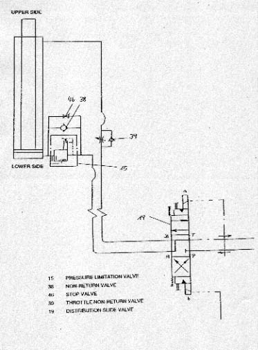
- When the distributing slide valves were moved (19) from right to left, oil would flow from the pressure pipes (P) to the piston undersides, the piston rods moved upwards and the visor opened. The oil at the piston rod sides flowed undisturbed through valves 39 into the return pipes (T).
- When the distributing slide valves were moved from left to right the oil flow reached in throttled condition (39) the upper cylinder chambers (piston rod side). The pressure in the upper cylinder chambers pushed the pistons downwards. Also the weight of the visor acted on the pistons. At the underside of the pistons overpressure developed as the stop valves (46) closed, the non-return valve (38) prevented oil flow in this direction and the pressure limitation valves (15) were not yet open. Only if excessive pressure had built up at the lower sides of the pistons would the pressure limitation valves (15) open and the visor move downwards.
- There were two reasons for the installation of such valves (15). On the one hand such valves prevented the rapid falling down of the visor in case of pipe and/or hose failures, on the other hand the visor was unable to close by its own weight only. Consequently it was possible to keep the visor in a partly open respectively closed position.
- In the case of the bow and the stern ramps, which were connected to identical hydraulic systems, it was the other way round because the weight of the ramps acted in the opening direction.
- In case the visor and bow as well as the stern ramps should be closed or kept closed by hydraulic pressure, the piston rod sides had to be pressurized and the actuators would retract respectively remain retracted.
The following diagram shows part of the von Tell drawing 49111-387 with the visor actuator - arrow 1 - and the bow ramp actuator - arrow 2 - with the respective hydraulic systems, as explained on the previous pages, fitted to the cylinders.
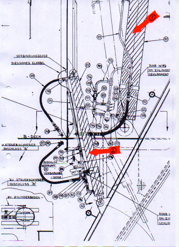
As these installations were located in the void spaces above and below B-deck as it is visible from the drawing on the next page, they were accessible for the crew. This means that it has been possible to manipulate the valves at the visor and bow ramp actuators from inside the side-houses without having to touch the control panel on the car deck. By means of the above explained "cross-over" effected at the aft hydraulic station - see Enclosure 2.4.2.31 - it has also been possible to put pressure on the cylinders of visor and bow ramp by means of the aft hydraulic station. In summary it can thus be concluded that it was possible to put pressure on the actuators of visor and bow ramp, i.e. to keep them closed by hydraulic pressure, without having to use the control panel on the car deck.
It can further be concluded that it was possible to keep visor, bow and stern ramps in a semi-open/-closed condition which, however, required the running of at least one hydraulic pump under continuous load changes (on/off). The visor actuators were connected to the vessel's B-deck by 2 lugs for each cylinder (see Enclosure 2.6.4.79 - photo showing B-deck).
Below this deck there were respective stiffeners and brackets fitted, which transferred the forces into the vessel's structure. To lift the visor 118 ts. were required at each cylinder. The maximum lifting power of 1 cylinder at a design pressure of 250 bar was 153 ts. The test pressure of the cylinders was 350 bar.
Note:
According to
the chief engineer Lars Karlsson the hydraulic pumps were changed in 1985/86
to more powerful ones which could produce a maxi-mum operating pressure of
400 bar. Reportedly the other components of the system remained unchanged.
- See Enclosure 2.4.5.60
- and the class was not informed although this was a significant manipulation
of the system.
Sensors/ indicator
lights/ control panels
At the time
of delivery the opening and closing procedures of bow visor and bow ramp were
controlled by in total 25 sensors of which 18 were magnetic limit switches
and 7 mechanical limit switches.
With reference
to part of drawing 49111-871 - attached as Enclosure
2.6.4.80 - these sensors shall be explained as follows: