|
| |
C. Other Examination / Investigation Reports |
| |
| |
| 16.The Disconnection of the Visor from the Vessel by Dr. Zenon Hirsch - Page 2 |
|
| |
 |
|
 |
|
 |
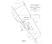
| Drawing 1.1 |
 |
| |
|
|
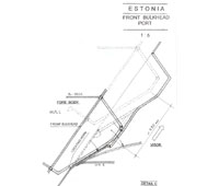
| Drawing 1.2 |
|
| |
|
|
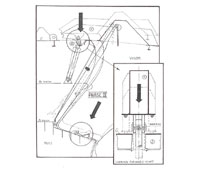
| Drawing 2.1 |
|
| |
|
| |
|
|
|
|
 |
|
 |
|
 |
| Drawing 2.2 |
|
| |
|
|
| Drawing 2.3 |
|
| |
|
|
| Drawing 2.4 |
|
| |
|
| |
|
|
|
|
 |
|
 |
|
 |
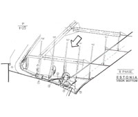
| Drawing 3.1 |
|
| |
|
|
| Drawing 3.2 |
|
| |
|
|
| Drawing 4. |
|
| |
|
 |
|
 |
|
|
| Drawing 4.2 |
|
| |
|
|
| Drawing 4.3 |
|
| |
|
|
|
| |
|
|
|
|
|
Phase III
- After having been raised by about 400-450 mm the visor moved down and forward (the hinges now broken) which caused the following:
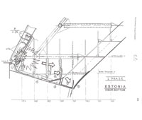
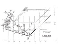
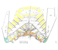
- The lugs of the visor actuators below the visor arms moved easily through the already cut away deck beam at frame 159 – see drawing 3.1 on page 228 and the photos on page 98.
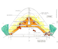
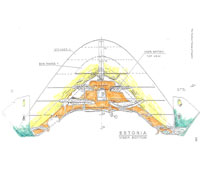
- The visor crashed back onto the forepeak deck more forward of the initial position, i.e. stempost and hull plating were over-lapping the forepeak deck, which caused the shell plates to be cracked off the visor bottom and the forepeak deck to deeply penetrate the visor bottom. See drawing 3.2 on page 229.The visor bottom was pushed upwards but held in place- by the still intact Atlantic lock which only broke later.
- The blown out steel flap – arrow 4 – on drawings 2.1 and 3.2 – was crushed flat when the visor settled on the forepeak deck.
|
|
|