29.2
The Bow Area
The following
damage description and evaluation is based on the video footage made by the
ROVs and divers as described in the previous Chapters 25, 27 and 28.
The
video films have been examined in close cooperation with Disengage - see Subchapter
34.6 - and images have been made of all relevant parts, which are arranged
on sheets in accordance with the following "areas of interest":
S 1 - Starboard
Visor Hinges
P 1 - Port
Visor Hinges
S 2 - Starboard
Harbour Securing
P 2 - Port
Harbour Securing
S 3 - Starboard
Forecastle Deck
P 3 - Port
Forecastle Deck
S 4 - Starboard
Front Bulkhead
P 4 - Port
Front Bulkhead
S 5 - Foundation
on B-Deck of the Starboard Visor Actuator
P 5 - Foundation
on B-Deck of the Port Visor Actuator
6 - The Bow
Ramp
7 - The Forepeak
Deck
8 - The Atlantic
Lock
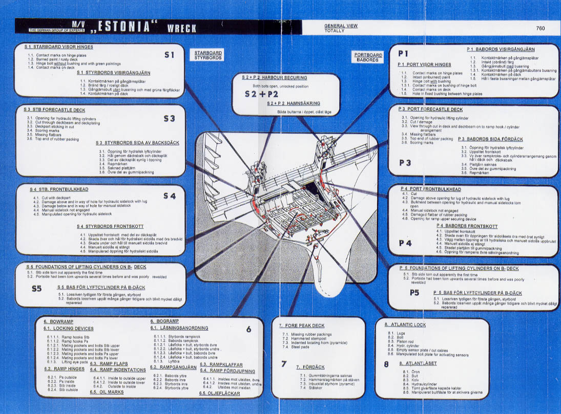
All the areas are
shown on a 'General View' attached behind the page after next. Furthermore
each "area of interest" is explained separately on one or more sheets, on
which numbered detailed photos are arranged around an overview drawing showing
the foreship of the wreck with slightly open bow ramp. On this drawing the
respective "area of interest" is indicated and on a further detailed drawing
this area is enlarged with added information. Thereby the numbers on the drawing
correspond to the numbers on the images.
In addition
to the information and explanation already provided by these sheets, the pictures
are evaluated and interpreted and, if considered necessary, other photos and/or
drawings are added.
The sheets
are arranged at the beginning of the comments and it is recommended to the
reader to look at these sheets when reading.
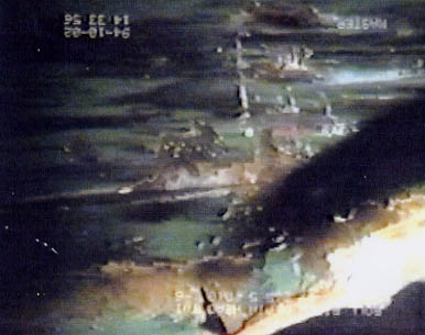
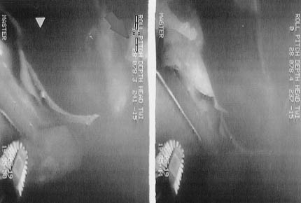
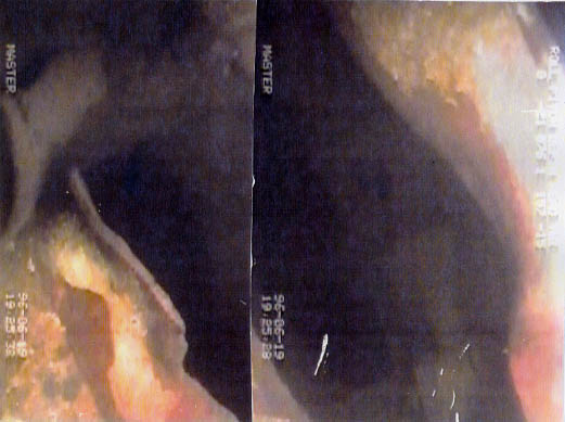
The authors do apologise
for the partly very poor quality which is due the faulty copying of the video
tapes from PAL format to PAL/SECAM without the use of a converter. - See Subchapter
34.6.
(click
for full page images)
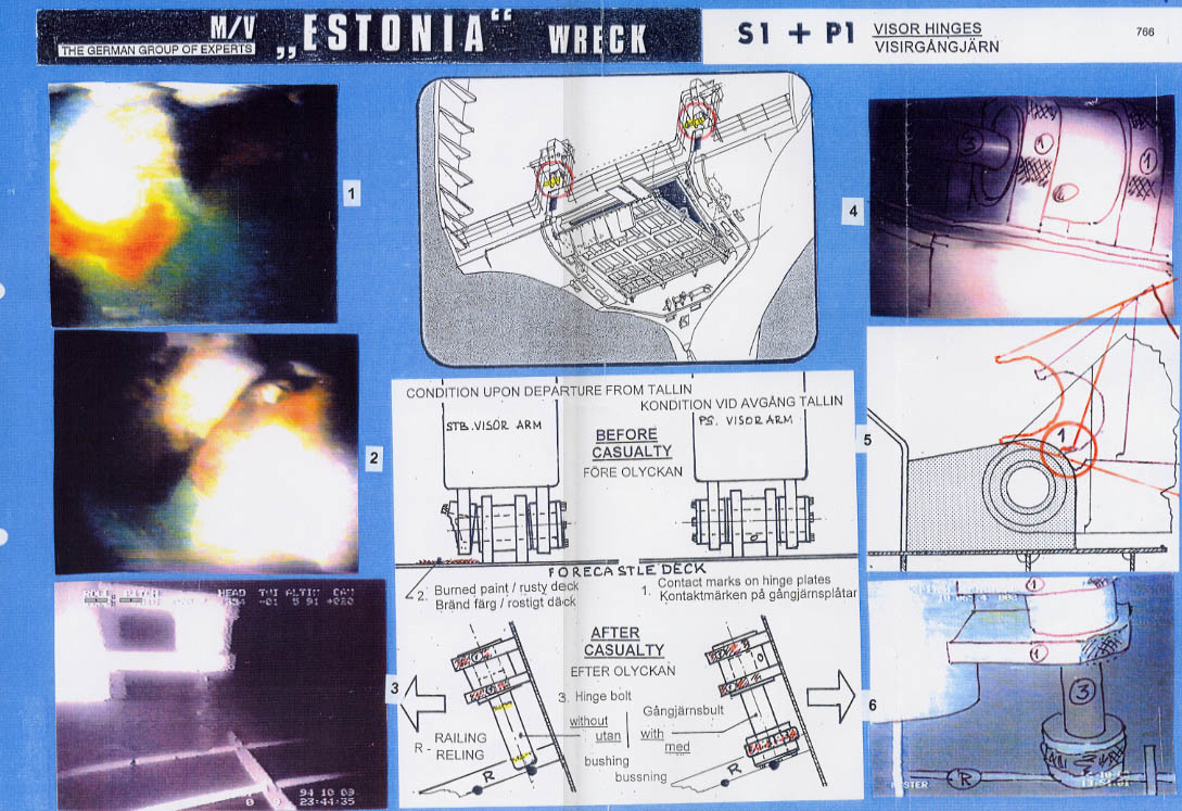
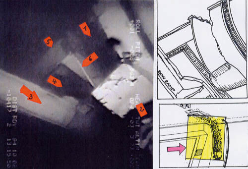
S 1 - Starboard
Visor Hinges
The technical description
of the intact visor hinges can be found in Subchapter 2.6.2, the damaged condition
is explained in Subchapter 12.5, whereby reference is made to the report of
Bryan Roberts - see Enclosure
12.5.180 - and to the enlarged images showing this hinge arrangement on
17.09.94, i.e. 10 days before the last departure. These enlargements are attached
as Enclosures
12.5.181/12.5.181.1.
Furthermore reference is made to the statements and the interview of Rain
Oolmets - see Enclosures
12.5.177-179.
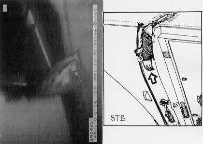
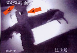
Interpretation: Images 1-4 show the two lugs with the fixed bushing
in between fitted on the forecastle deck which are facing forward. Both lugs
show hammering/scoring marks (1), which were, in all probability, caused by
the broken parts of the visor hinge plates and the aft end of the visor arm
lower closing plate. - See the drawing below.

In addition images
2 and 4 show an area of burnt deck paint to starboard of the outer lug plate,
i.e. below the location of the bushing in normal condition. This indicates
that flame cutting had been carried out that close to the deck that the paint
became burnt.
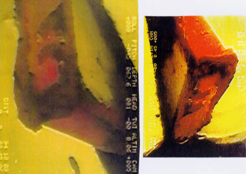
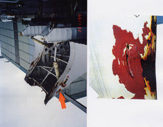
Images 5 and
6 show the middle and outer part of the hinge bolt (3). The bolt moved out
of the hinges due to the list of the wreck and is ever since standing on the
adjacent railbar. There are three areas of green paint visible which are indicated
by red dots. Since only the deck was painted green it has to be assumed that
the green paint visible on the bolt was deck paint. The hinge arrangement
was a closed system without gaps between bushings and lug plates. This was
evidently no more the case when the green deck paint was able to reach the
bolt at least in three places! The explanation that this was possible can
also be found in Subchapter 12.5 and on the enlarged images attached as Enclosures
12.5.181/12.5.181.1,
i.e. the starboard visor hinge arrangement was totally misaligned with the
outer bushing sticking out too much which created the gaps between hinge plates/bushings
enabling the green paint to reach the bolt. The condition of the outer part
of the outer bushings of which the lower part was evidently cut off explains
the following:
(a) The bolt had
only to some extent engaged the outer visor hinge plate.
(b) The burnt
off lower part of the bushing made it possible for the bushing to fall off
the bolt (contrary to the port where the bushing was intact and consequently
remained attached to the bolt - see the following item P 1).
(c) During the
flame cutting (burning) of the lower part of the said bushing the deck paint
below the bushing was burnt because of the narrow distance between the lower
part of the bushing and the green deck.
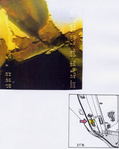
Image 4 shows also
scoring marks on the deck in front of the hinge plates evidently caused by
the visor arm lower closing plate during opening/closing of the visor. This
indicates that the visor was too low in the hinges, a consequence of the burnt
out hinge plates. - See Chapter 30.
(click
for full page images)
P 1 - Port
Visor Hinges
The technical description
of the intact visor hinges can be found in Subchapter 2.6.2 and some indications
about damage can be found in Subchapter 12.5 and in the statements and interview
of Rain Oolmets attached as
Enclosures 12.5.177-179.
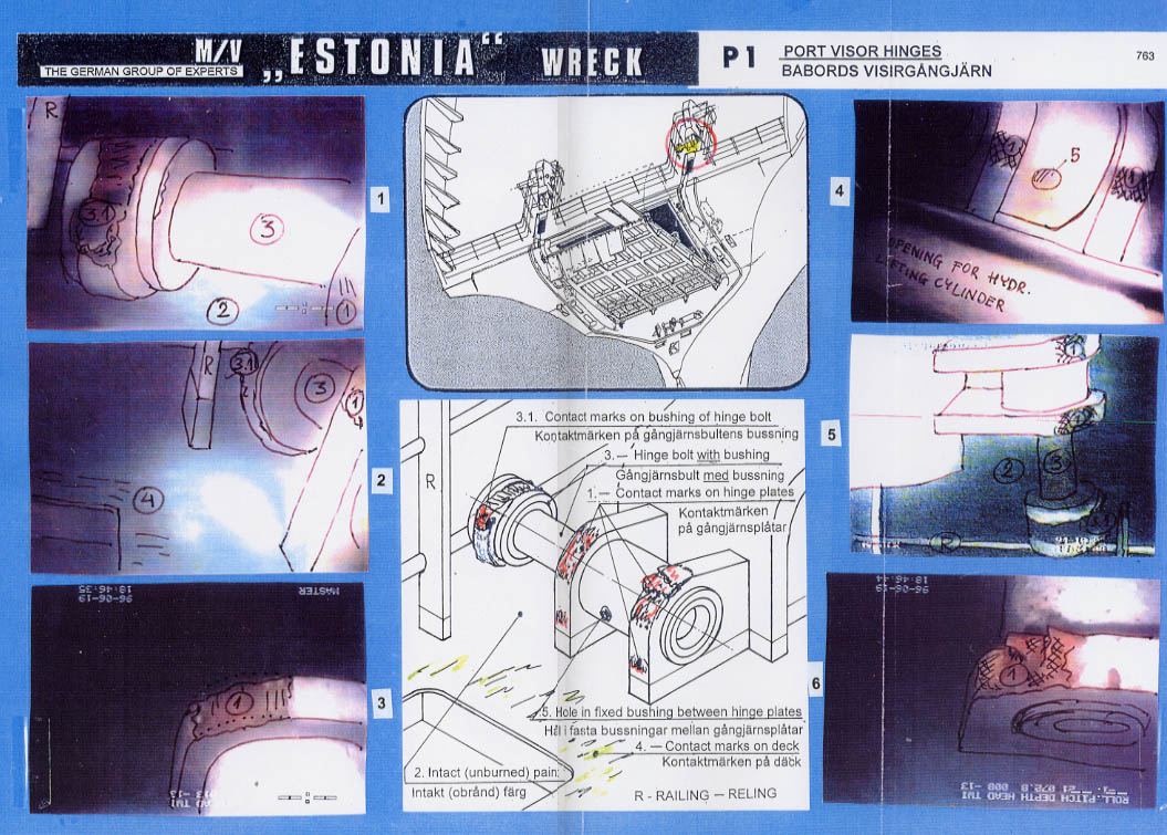
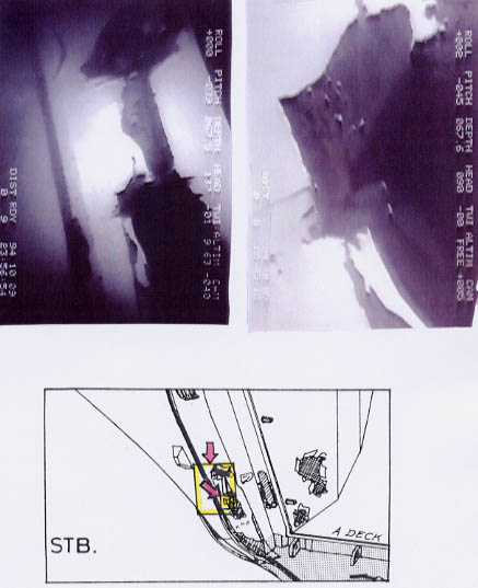
Interpretation: Images 1-5 show the port hinge bolt moved out of the
hinge plates/lugs and resting on the adjacent railbar, however, contrary to
the starboard side - without green paint but with the inner bushing still
attached to the bolt.
No. 1 shows
in addition severe hammering/contact marks in way of the fracture area of
the visor hinge plates still attached to the bushing; (item 3.1. on the detail
drawing)
the counterpart
at the visor side was the lower part of the inner hinge plate in way of the
fracture area which is pictured below.
The upper and lower
parts of the outer hinge plate do not show signs of hammering or contact.
This will be demonstrated in more detail on sheet P 3 - Port Visor Arm - See
Chapter 30.
No. 2 shows two
areas of interest, viz.
(a) the
deck area below the previous location of the bushing with the green deck
paint undamaged; i.e. not burnt. (item 2 on detail drawing)
(b)
the rubbing respectively contact marks between the deck opening and the
hinge plates, most probably caused during the normal operation by the too
low visor arm as a further result of the completely misaligned visor.
(item 4 on
detail drawing)
No. 3 shows the moderate
contact marks at the upper part of the inner hinge plate.
No. 4 shows the
two hinge plates with the fixed bushing in between (diver looking out of the
deck opening for the port lifting cylinder); the hole in the fixed bushing
(item 5 in detail drawing) should be noted which most likely was cut into
the bushing to reach the bolt with oil and grease for lubrication purposes
(see statement 2nd engineer Peeter Tüür - Enclosure
12.5.167); also the contact marks at the lower part of the hinge plates
(item 1) should be noted whereby it is obvious that the outer (port) marks
are higher than the inner (starboard) ones.
No. 6 shows severe
hammering marks at the upper part of the outer hinge plate (item 1) evidently
caused by the visor closing plate. - See the drawing below.

(click for full page
images)
S 1 and
P 1 - Visor Hinges
The sheet demonstrates
the condition of the port and starboard visor hinges upon departure from Tallinn
on 27.09.94 and the condition of the hinge parts on the forecastle deck of
the wreck as found after the sinking.
Images 1-3 on the left side show the starboard hinge parts with hinge bolt
evidently without attached bushing, i.e. the bushing fell off the bolt
after the visor hinge plate were broken.
Images 4 and
6 show the forecastle deck parts of the port visor hinges with the hinge
bolt evidently with attached bushing.
The drawing
No. 5 demonstrates the various hard contacts between the broken parts of the
visor hinge plates and the fixed lug plates on the forecastle deck.
(click for
full page images)
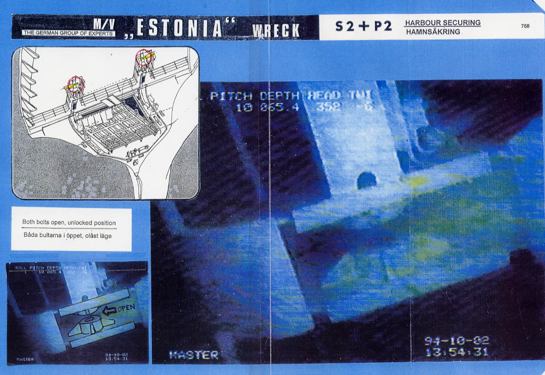
S 2 and
P 2 - Harbour Securing for Visor
The sheet shows
two pictures of the open port and starboard harbour securing. It is clearly
visible that both bolts are open. When the visor was opening, a strong lug
on top of each of the visor arms moved between the mating parts of the harbour
securing, a sensor was contacted and activated a green light on the car deck
control panel indicating "visor open", whereupon the operator closed the bolts
of the harbour securing hydraulically and the red light, indicating "harbour
securing open", went out and the green light, indicating "harbour securing
closed", went on. When the visor was closed the sequence was the other way
around, i.e. when the bolts moved into the open position before the visor
was closed there was no more contact with the sensor and on the control panel
the green light went out and the red light went on indicating "harbour securing
open". The red light remained on until the sensor was again in contact with
the bolt during the next opening of the visor.
(click for full page images)
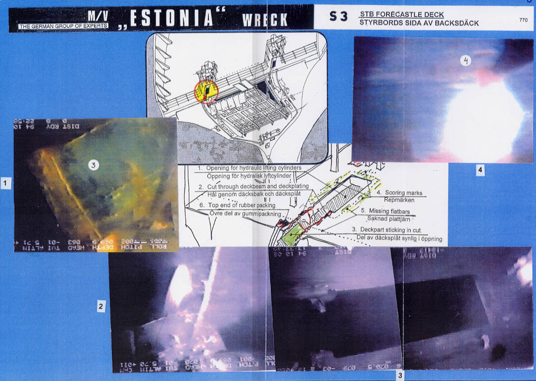
S 3 - Starboard
Forecastle Deck
The area under investigation
is restricted to the deck opening for the lifting cylinder of the visor (actuator)
and forward towards the deck edge as indicated on the overview drawing and
on the detailed drawing.
The sheet shows
the images 1, 2, 3, 4 of which No. 3 has been compiled together from two images
in order to be able to show the entire deck opening of the cut through deck
beam at frame 149.
Interpretation:
Image No. 1 and
2 show a pieces of green deck paint, probably from B-deck, which obviously
fell into the as-found position only after the actuator had moved forward
through the big hole in the front bulkhead - see sheet S 4. This raises
the question what caused such a big steel piece to break off the B-deck?
This will be answered in Chapter 32 - Unexplained Damage / Unexplained Evidence.
No. 3 shows the
opening in the forecastle deck from the deck beam at frame 149 to the forward
aft end in front of the lug plates of the visor hinges, welded to the forecastle
deck. Attention had to be drawn to the apparently unaffected edges of the
opening aft of the deck beam and the remains of the quite strong deck beam.
Note: Computer
simulation and calculation to determine the force required to break through
this deck beam have been carried out by the Technical University Hamburg-Harburg
and are commented in Subchapter 34.11.
Contrary to the port
opening - see sheet P 3 - where the ramp hook arrangement is clearly visible
when the ROV looked into the opening - see the image on the next page - the
starboard opening is just a big black hole. This can only mean that the starboard
ramp hook was not where it was supposed to be.
Also the flat bars
around the deck opening into which the rubber packings - fitted below the
visor arm - should be pressed, when the visor was closed, were missing. The
same refers to the flat bars having initially been welded athwartships at
the forward part of the forecastle deck into which the rubber packings at
the aft part, i.e. below the recess of the visor, should be pressed when the
visor was closing (see also item 5 on the detail drawing). This can be seen
from the following two pictures, of which the first one shows the starboard
aft part of the visor deck with untouched rubber packings, intact and in place
and the 2nd is the port side which is evidently in worse condition.
The picture below
shows the rubber packing underneath the starboard visor arm which was obviously
never pressed into any flat bar and is not affected at all, which confirms
the apparent fact that
a) the flat bars
around the deck opening had been removed prior to the casualty and that
b) the visor
was raised to some extent at this side after the hinges were broken since
otherwise this rubber packing would have been destroyed as it did happen
at port side - see P 3 - Port Side Fore-castle Deck.
No. 4 shows
the area between the hinge plates and the deck opening which is evidently
covered with numerous rubbing marks caused by the opening and closing of the
visor during normal operation.
(click for
full page images)
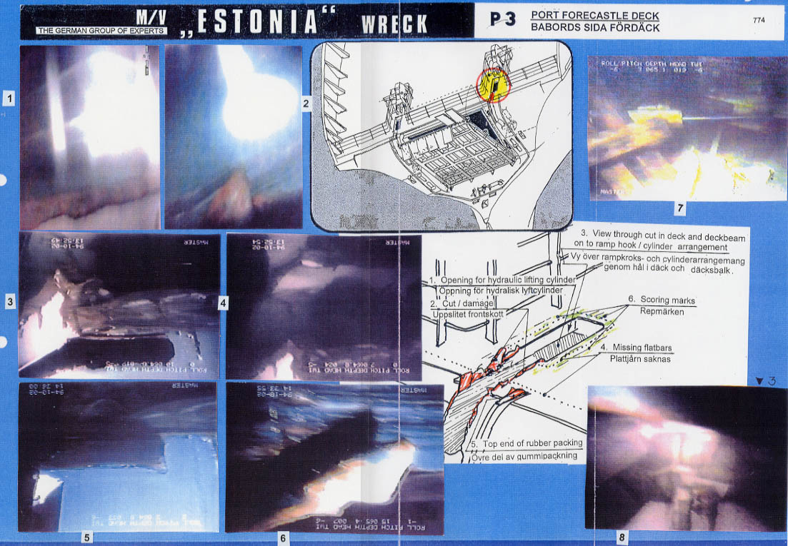
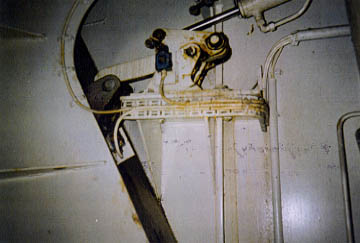
P 3 - Port
Forecastle Deck
The area under investigation
is restricted to the deck opening for the lifting cylinder of the visor and
forward towards the deck edge as indicated on the overview drawing and on
the detail drawing.
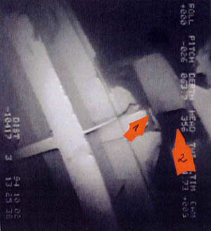
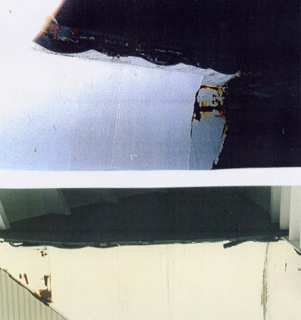
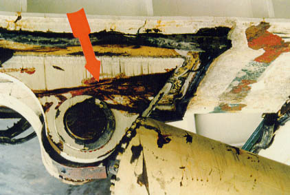
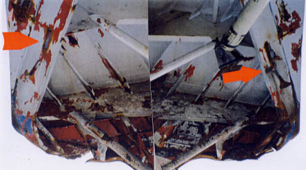
The picture below
shows the area with the deck beam (arrow 1), the forward edge of the deck
opening (arrow 2), the visor lug (arrow 3) and actuator (arrow 4) in its original
sound condition.
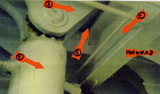
Image No.
1, 2 and 6 show the starboard inner side of the cut through the deck beam
at frame149, which are evidently pressed together, partly cracked and bent
up, indicating pressure from port to starboard. The edges of the deck opening
aft of the deck beam are not affected at all, same as on the starboard side.
This is only indicated on the detail drawing but is clearly shown on the available
video footage. The starboard side of the cut through deck beam and the deck
plating as well as the rubber marks are shown also on the picture below.
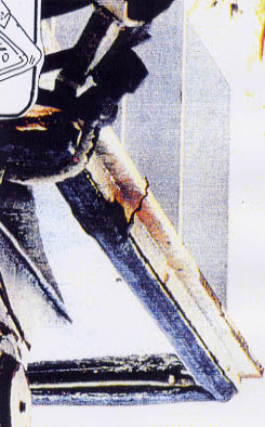
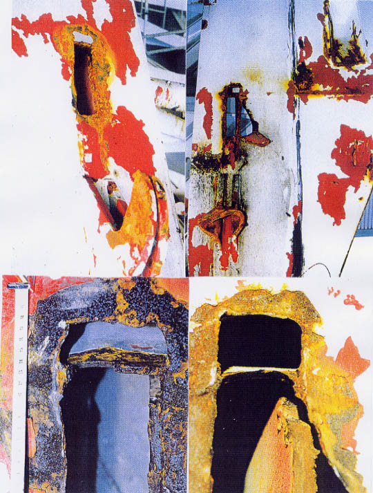
It must have
taken some time for the visor lugs to cut through this deck beam while the
visor moved forward/aft in the sea state ending when the visor lug plates
had finally cut through this strong deck beam. It has to be assumed that during
this cutting process at least the paint on both the inner and the outer lug
plates should have been destroyed in way of the contact area. This was, however,
evidently only the case with the inner lug plate as can be seen on the picture
overleaf.
Note: As
to the forces required to break through this deck beam see Subchapter 34.11.
The lug plate
has very deep and - at the upside - straight scoring marks, almost engraved,
which indicate
(a) the movements
of the visor and
(b) that
the weight of the visor was to some extent resting on this inner lug plate
which caused these very deep scraping marks, whilst the opposite side, i.e.
the outer lug plate, remained completely unaffected as visible on the next
picture.
This outer lug plate
does not even show scratches, i.e. the paint is totally intact.
This will
be discussed in more detail in Chapter 30 - Damage to the Visor - where also
other pictures are shown.
Images No. 3, 4
and 5 show the forepart of the cut through the deck plating and down the front
bulkhead with the rubber packing of the visor in way.
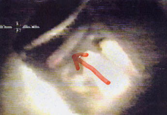
No. 7 shows the
view of the ROV into the deck opening with the ramp hook arrangement clearly
visible.
No. 8 shows the
view of the diver onto the same area from a slightly different angle. At the
upside the more or less unaffected port edge of the opening is visible, at
the downside the remains of the deck beam are visible. It is evident that
the hydraulic cylinder of the ramp hook was in extended condition, i.e. the
ramp hook was in looked condition.
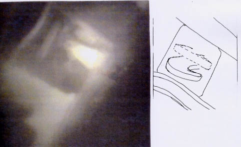
From subsequently
obtained video footage - evaluated by Disengage - it was ascertained that
the port ramp hook was intact and complete, i.e. neither broken nor bent straight.
This means that this hook had not been engaged in its mating lug because this
lug is also intact with the bolt undamaged. - See also item 6. The following
image shows the intact ramp hook, the adjacent drawing explains the image.
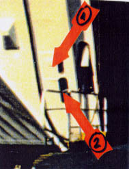
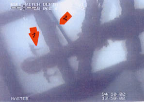
The following
picture shows the misalignment between the mating lug at the ramp side and
the opening in the front bulkhead out of which the hook would extend, i.e.
it was impossible for the hook to engage the mating lug in this condition.
This explains the undamaged condition of both hook and mating lug.
Arrow 1 points to
the mating lug at the ramp
Arrow 2 points
to the location where the hook would reach out of the opening
Note: The
4 inches = 100 cm misalignment between the bolts on the ship's side and the
mating pockets on the port side of the bow ramp as reported by the diver must
logically exist also between the ramp hook on the ship's side and the mating
lug on the bow ramp. This is further evidence that neither the bolts could
have engaged the mating boxes nor the ramp hook the mating lug on the port
side.
In order to be able
to compare the "original" with the "as-found" condition reference is made
to the photo below.
S4 -Starboard
Front Bulkhead
The area under investigation
is restricted to the starboard front bulkhead of the wreck as shown on the
drawing below. There is no sheet available for this area. For easy reference
the explanations will be given by photos/video images incorporated into the
text. The numbers on the drawing indicate the damage areas which shall be
explained and illustrated as follows:
Area No. 1
shows the cut at the edge of the forecastle deck down to the front bulkhead
with a deck piece sticking into it and in the front bulk-head further down.
Area No. 2
shows the damage further down the front bulkhead. Note the torn open steel
bent to starboard and to port.
The arrow on the
left picture points to the severely distorted mating lug for the ramp hook.
The three images
on this page show details of this large damage, in particular the bent and
cracked steel parts at the edges.
The picture
below shows the lowest part of the damage, i.e. an almost horizontal, slightly
upwards pointing steel flap.
Area No. 3
shows the damage above the torn off lug being part of the hydraulic side lock
of the visor, the lug itself and the opening for the manual side lock. The
most probable cause for these damages is explained in Chapter 32.
The following image
shows the big hole above the opening for the lug of the hydraulic side lock
which extends beyond the bulkhead edge. - See arrow.

The previous image
shows an enlargement of this hole with the bulkhead pushed upwards (inside
to outside) creating a big gap towards the lug of the side lock, the plating
in way is cracked - see arrow 1. At the bottom of the picture the upper part
of the lug of the hydraulic side lock of the visor, torn off the visor, is
visible. Arrow 2 points to a small white painted steel piece originating from
the visor bulkhead.
Note:
According to the
diver - video tape B40c - this small steel piece was the only part of the
starboard aft bulkhead torn off when the lug separated from the bulkhead.
See the following page.
The next images
show the lug of the hydraulic side lock which was evidently torn off the visor
bulkhead together with the welding seams by which it had been welded to the
bulkhead.
Note: When
the diver examined the area of the starboard side lock the following discussion
developed between the supervisor in the operations room and the diver.
Supervisor: "How
many mm's play?"
Diver: "About
10 mm."
Diver: "It
has ripped the weld, there is no plate there at all (pointing to the very
thick welding seam at the lug). That's the edge of the weld."
Supervisor:
"So it hasn't taken away anything of the bulkhead, but just ripped the weld
off."
Diver: "That's
right."
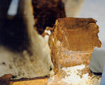
The picture shows
the lug with very thick welding seams by which it had been attached to the
visor bulkhead.
Note: It is
obvious that these welding seams do not originate from one welding procedure
only but from several weldings on top of each other, i. e. after each cutting
off the new weld was laid on top of the previous ones without grinding off
the remains of the previous welds as required by proper workmanship to assure
the required load-carrying capacity of the weld. The required load-carry capacity
of these lugs being part of the locking system of the visor did already since
sometime before the last departure no more exist and was reduced to a fraction
of the initial load-carrying capacity by such unqualified repairs.
The two pictures
below show this part of the visor bulkhead, the 1st one from the top and the
2nd one from the side.

The next image shows
the broken bulkhead part between the opening with the lug of the hydraulic
side lock and the much enlarged opening for the manual side lock below.
The following pictures
show the upper part of the enlarged opening for the manual side lock.
Note the steel
bent from inside to outside.
The two pictures
below show the enlarged opening for the hooks of the manual side locks with
the steel plating bent from inside to outside and the edges cracked.
On the right picture
the not engaged mating part of the manual side lock is visible in the background.
Furthermore a "soft" indentation can be seen on the inside of the substantially
enlarged opening.
Next pictures follow
which show the starboard lower aft bulkhead of the visor having been directly
opposite to the corresponding parts of the starboard front bulkhead of the
wreck. In comparison also the port lower aft bulkhead is shown.
The picture on the
right left shows the are of interest on the starboard side, the picture on
the left shows the corresponding port side. It shows a completely different
damage picture: no smoke marks, no steel tongue torn off the bulk-head and
no twisted hooks.
Two of the
following four pictures on the next page show those areas at the port and
starboard aft bulkhead of the visor where the lugs of the side locks had been
welded to and the hooks for the manual side locks were fitted. The other two
are close-ups of the upper parts of the area where the lugs had been welded.
The right side shows the part of the starboard visor bulkhead directly opposite
the above explained damage area. The smoke marks are still clearly visible
although the visor had been on the sea bottom for 7 weeks. The hooks are distorted
in a way which is technically not explainable. The area is dark. The picture
on the left shows the corresponding port side as comparison with a complete
different damage picture, with no smoke marks, no steel tongue torn out of
the bulkhead and no twisted hooks and a generally clean appearance. The two
close-ups arranged below the above mentioned photos show the respective upper
parts of those openings in the bulkhead. They do illustrate the difference
very clearly. While the port side shows normal steel clean of corrosion, the
starboard side shows steel which had obviously been exposed to heat and pressure
force: The metal is distorted and pushed out, the stiffener is detached from
the bulkhead. See also Chapters 30 and 32.
Area No. 4 concerns
the lower part of the front bulkhead which evidently became bulged forward,
with cracked welding seams and consequently cracked off the hull plating,
the forepeak deck and the recess of the longitudinal bulkhead by forces explained
in Chapter 32. Part of this considerable damage is shown by the image below
and the adjacent drawing.

The above image is
explained by 4 arrows, viz.
No. 1 - lower part
of the opening for the manual side lock
No. 2 - transverse
crack in the front bulkhead
No. 3 - cracked
open part in way of the flatbar channel for the rubber packing
No. 4 - deep
fold between front bulkhead and hull plating indicating that the bulkhead
was bulged out.
The following two
images show the area indicated by arrows 3 / 4 on the previous image in some
more detail.

The two images on
the next page show the condition of the lower parts of the port and starboard
front bulkheads. The left one shows the lower part of the starboard front
bulkhead - arrow 1 - the rubber packing channel - arrow 2 - and the hull plating
in way of the change-over from white to blue - arrow 3. The lower white part
indicated by arrow 4 was apparently cracked off the bulkhead. The right image
shows the corresponding part of the port front bulkhead in apparently undamaged
condition.

It is quite obvious
that the starboard bulkhead is cracked off the forepeak deck, is extending
further forward and downward and that a the white part - arrow 4 - as part
of the bulkhead is totally misplaced.
Note: It
is not possible to verify this very substantial damage further by means of
the video footage available.
Area No. 5 concerns
the opening for the starboard bow ramp actuator which is directly below the
severely damaged landing of the ramp with the fastenings for the actuator.
The left image below
shows the upper part of the opening - see arrow - which is obviously undamaged.
The right image
shows the lower part of this opening with the edges bent from inside to outside
and the adjacent plating severely deformed to the effect that the initial
shape is no more recognisable.

arrow 1
points into the centre of the opening
arrow
2 points to the bow ramp
arrow 3 points to the longitudinal part of the recess in the front
bulkhead
The picture below
shows the intact starboard front bulkhead in July 1994. Note that in way of
the opening for the lug of the hydraulic side lock a plate had been inserted
with a doubler in the middle (arrow 1). The background of this repair is unknown,
could mean, however, that the lug once had smashed into the bulkhead, when
the visor was misaligned, e.g. due to lifting cylinders working asymmetrically.
Arrow 2 points
to an indentation at the rail of the movable forward section of the bow ramp.
A similar indentation also exists on the corresponding port side. This means
that the visor was lowered down to that level for work to the bottom and hull
side, e.g. to repair and paint ice damage, although the bow ramp was open.
This means that the electric blockage installed at newbuilding had been bypassed.
It had been installed to prevent that the visor could be closed when the bow
ramp was still open, respectively that the bow ramp could be opened (to a
certain extent) when the visor was still closed. See also the von Tell Manual
- Enclosure 2.4.2.31 and the statement of Lars Karlsson - Enclosure 2.4.5.60.
Area No. 6
concerns damage to the longitudinal car deck bulkhead which will be explained
in Chapter 32.
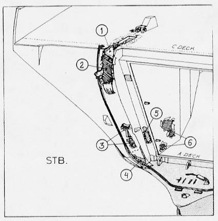
P 4 - Port Front
Bulkhead
The area under investigation
is restricted to the port front bulkhead of the wreck as shown on the drawing
below. For easier reference the explanations will be given by photos/video
images incorporated into the following text. The numbers on the drawing indicate
the damage area, which shall be explained and illustrated as follows:

Area No.
1:
The following
picture shows the upper part of the cut in the front bulkhead - arrow 1
- caused by piston rod and lifting cylinder, the lower part and the folded
together steel strip torn out of the bulkhead - arrow 2.
Generally the damage
appearance is totally different on this side compared to the starboard side.
Whereas the cut at port side looks as if having been cleanly made in one go
by a large can opener, the damage picture on starboard side demonstrates violent
movements, heavy distortion to the starboard side, etc.
Arrow 3 points to
the slightly open bow ramp, arrow 4 to the car deck opening and arrow 5 to
the forecastle deck.
Arrow 6 points
to a wire running from forecastle deck down beside the bow ramp, which was
no more there when the divers came.
The next images
show the lower part of the cut with the rolled up steel strip and with a rope
around it rising up at both sides.

Area No. 2
- concerns
the opening in the recess of the front bulkhead for the ramp hook. The hook
has been identified inside this opening. The red arrow on the image below
is pointing to the hook which is obviously intact and in locked condition.
The image
above is a view into the opening in the front bulkhead recess inside of which
the port ramp hook should have engaged the mating lug at the ramp during the
closing procedure which it evidently did not do during the last voyage. This
has already been explained under P 3 - Port Forecastle deck.
Note: The
damage at the lower part of the port front bulkhead adjacent to the port outer
hinge of the bow ramp shall be discussed under 6 - Bow Ramp.
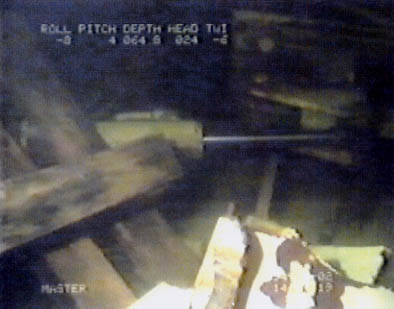
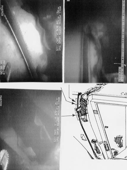
The image below was
made when the ROV looked into the opening in the forecastle deck for the port
visor actuator. The actuator of the ramp hook with part of the hook arrangement
and the remains of the cut through deck beam - see arrow - are clearly visible.
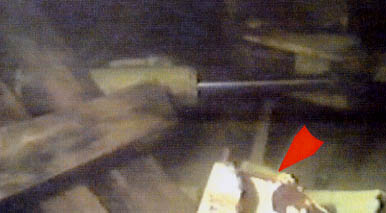
Note: When
the ROV looked into the corresponding deck opening for the starboard visor
actuator only the remains of the cut through deck beam were visible. The ramp
hook arrangement was obviously no more in place.
Area No. 3:
The following image
shows transverse contact marks above the opening for the hydraulic side lock
- see arrow 1 - which presumably resulted from the visor moving forward/aft
during the time it took the visor arm lugs to cut through the deck beam.
Arrow 2 on
the above image points to a wire running across the front bulkhead and the
bow ramp to the starboard side and apparently from the port fair leads of
the forecastle deck (there is no other possibility where a wire could come
from). The image was made from the video tape produced by ROV on 02.10.94
- see Subchapter 25.1 - because on subsequent videos the wire is no more visible.
The next image -
made from the same video tape - shows the same area, but slightly further
down (in normal condition). Arrow 1 points to a double rope coming up from
the gap between bulkhead/ramp and rising up due to its floatability.
Arrow 2 points
to a damage area in way of the rubber packings which is better visible on
the right image below made from the 1996 video tape. The double rope was then
still there because it is jammed in, though in slightly changed position.
The damage area is more clearly visible - see arrow.
The left image
above was taken from diver video B40c and is a close up of the same damage
area. It shows that the rubber packing including flat bar channel has been
pressed flat on a distance of about 200 mm. This could have been caused by
a single wire or wire running from the bow ramp around the edge of bulkhead/hull
plating up to the fair leads on the forecastle deck and further to one of
the winches. Alternatively the damage could have been caused by the port aft
edge of the visor bottom in the final stage of the visor separating from the
vessel - see Chapter 31 - or it could have been an old damage because the
corresponding area on the aft bulkhead of the visor does not show rubbing
marks from the rubber packing. See the picture on the next page. A similar
damage does not exist at the starboard front bulkhead.

The next image
shows the lug of the hydraulic side lock still attached to the locking bolt
with a little part of the visor bulkhead (white) - see arrow - and visible
welding seams. The lug is - contrary to the starboard side - inside the bulkhead
and was only subsequently pulled out by the diver.

It revealed that
this lug had similar thick welding seams - same as the starboard one according
to the diver and that also here only a small piece of the visor bulkhead was
pulled out - see arrow.
The next image shows
the locking bolt with nut of the manual side lock resting inside the vessel
evidently also not having been engaged during the casualty voyage.

Area No. 4
concerns the opening
for the bow ramp actuator in the recess of the front bulkhead. This is explained
in detail under - The Bow Ramp - in this chapter further aft.
Area No. 5
concerns a lug
welded adjacent to the broken port outer visor hinge and through which a
wire was found running. Also this will be explained in detail under - The
Bow Ramp - in this chapter further aft.
Area No. 6
concerns damage
in way of the port car deck bulkhead which will be explained and documented
in detail in Chapter 32.
(click for full page
images)
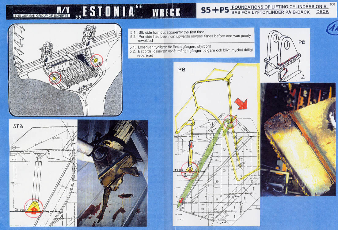
S 5 and P 5 -
Foundation of the Port and Starboard
Lifting Cylinders (Actuators) on B-Deck
The area under investigation
is restricted to the foundations of the two actuators on B-deck as indicated
on the overview drawing.
Pictures:
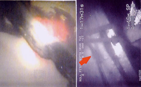
No. 1 shows the
foundation of the starboard actuator of the visor, which only broke loose
at a late stage as it is evident from the damage visible;
No. 2 shows the
foundation of the port actuator which looks totally different from the starboard
one and which had been repair-welded before. It is evident that this foundation
separated from B-deck quite easily due to pre-damaged and badly repaired
welding seams.
port
+ starboard

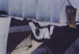
The port actuator
was found jammed inside the port longitudinal bulkhead as can be seen on the
photo below. It was completely pulled together.

The starboard
actuator, to the contrary, was found to be fully extended with the piston
rod bent. It had apparently been the last connection between the vessel and
the visor except for the bow ramp, the fore-castle deck and bulbous bow.
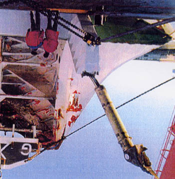
The area indicated
by the arrow and the close up was probably struck by the foundation of the
starboard actuator after the actuator had moved out of the front bulkhead
of the vessel. - See also Chapter 30 - The Visor.
6.The Bow Ramp
The area under investigation
is restricted to the bow ramp and the adjacent plating of forecastle deck
and forepeak deck as well as the front bulkheads on both sides, as can be
seen on the picture below showing the area in question, (photo was taken on
25.03.94 in Tallinn when it was snowing) and indicated on the overview drawing.
The following
diagram is part of drawing 49111-330 which shows the bow ramp in open and
closed condition. The areas of interest are divided into 6 parts, viz.
(1) The locking devices
(2) The actuators
(3) The hinges
(4) Damage
to the construction
(5) The rails
(6) Other observations