2.6
Visor
and Ramp Installations
2.6.1 General
The visor and ramp installations of the ESTONIA were of a configuration common on ferries in traffic between Finland and Sweden at the time of her construction. The installations comprised an upward-opening bow visor and a loading ramp at the bow and two loading ramps at the stern, which were hinged at car deck level and closed when raised.
In closed position, the upper end of the bow ramp extended into a box-like housing on the deck of the visor, the ramp house. The complete bow ramp and the operating and locking devices for the visor as well as the stern ramps and the hanging decks were designed and delivered by an independent company, von Tell Trading & Co. AB, Gothenburg (hereafter called von Tell AB), an established supplier of hydraulically operated ship's installations. The design was based on a detailed specification by the shipyard. Von Tell AB used a subcontractor, Grimmereds Verkstads AB, Gothenburg for manufacturing complete sets of components for the ramps, the hanging decks and the locking devices, including those for the visor. The routine contacts between the Yard and the supplier were via von Tell GmbH, Hamburg, a subsidiary of von Tell AB. Incorporation of the system into the ship and manufacture of the attachment structure were shipyard work, although under the supervision of a von Tell representative. See Subchapter 2.4.2. The equipment delivered by von Tell was identical to that built for the preceding newbuilding, DIANA II, except for the slightly increased length of the bow ramp and the changes of the car platforms dictated by the greater length of the vessel. According to available information the visor operating and locking system for DIANA II was designed by von Tell AB staff who had experience with similar installations from their previous employments.
The Bureau Veritas rules valid at the time had no details regarding procedures for calculating sea loads on the bow visor. It was stated in general wording "that doors should be firmly secured and that structural reinforcements should be made to attachment points of cleats, hinges and jacks". The general wording in the rules also specified that the scantlings for the visor structure should be equivalent to that of the hull itself.
The vertical and longitudinal sea loads to which the bow visor could be exposed were calculated separately by the Yard and by von Tell AB. The Bureau Veritas rules gave no detailed guidance for such calculations. The Yard therefore used for this purpose the nominal "pressure heights" given by Bureau Veritas in the Note Documentaire BM2 of 05.04.1976, which was originally issued as a general guidance for determining the loads on the bows of large ships, whilst von Tell AB used nominal pressure heads per unit of projected area specified in the rules of Lloyd's Register Shipping, valid at the time ESTONIA was under construction. For further details see Subchapter 2.4.2.
2.6.2
Technical description of the visor
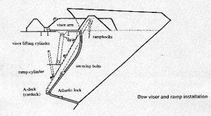
Bow visor and ramp installation
The Visor Construction and Functioning
The vessel was a Ro-Ro passenger ferry with visor, bow ramp and stern ramps. The visor was the most forward part of the vessel and pivoted around 2 hinges fitted at the forecastle deck, i.e. C-deck, having its opening and closing move-ments performed by 2 hydraulic lifting cylinders (actuators). The construction of the visor corresponded to the construction of the bow with material dimensioned according to the general requirements of the Classification Society (for details see Subchapter 2.4.3). The lower forward part was ice-strengthened. The visor consisted mainly of shell plating being an extension of the ship's shell plating and contour, the forecastle deck, the bottom part, the 2 aft bulkheads, the 3 horizontal stringers with the 5 bow pointers in between respectively on top of the 2 vertical partial bulkheads and transverse stiffeners. The two so-called visor arms (beams) extended about 3 m aft of the visor and ended in the two hinge arrangements by which the visor was connected to the vessel and which were the pivoting parts as well. The design weight of the visor was about 55 mts.
Between the two visor arms a box-shaped housing - the so-called ramp house - was fitted into which the upper end of the bow ramp extended in closed position. This was the interlock between visor and bow ramp, a configuration quite common at the time VIKING SALLY was designed and built (see Enclosure 2.6.2.67 - photo VIKING SALLY). In closed position the visor was connected to the foreship by three hydraulically operated locking devices. One of these locking devices - the "Atlantic lock" - was mounted on the forepeak deck - A-deck - whilst the other 2 were side locks mounted in the front bulkheads of the vessel with the mating lugs at the lower parts of the aft bulkheads of the visor.
In addition, there were 2 mechanical locking devices - the so-called manual side locks - mounted on both sides below the hydraulic side locks. The manual side locks were - according to Bureau Veritas - "Heavy Weather Securings" (see Enclosure 2.4.3.37 - letter B.V. to the JAIC dated 10.01.95 and Enclosure 2.6.2.75 - photo showing mock-up of the manual side lock).
Three strong locating horns - one on the forepeak deck called "pyramid" and one at each front bulkhead of the vessel - engaged recesses in the visor bottom respectively on both aft bulkheads of the visor when in closed position and were intended to absorb lateral loads.
In closed position the visor bottom rested on the forepeak deck mainly in way of the strong stempost which took about 75% of its weight, whilst two steel pads welded to the forepeak deck at the aft part of the visor bottom took a further ca. 20% and the remaining 5% were absorbed by the rubber packings. The visor was kept down by its weight and the 3 (or 5) locking devices which pulled the visor tight against the rubber packings on forepeak deck and both front bulkheads. Thereby any possible play was eliminated and the visor's inside was kept watertight. Forces acting in the forward/aft direction on the visor were transferred by the hinges, the locking devices and the front bulkheads into the structure of the vessel.
In open position the visor was secured by 2 parking devices consisting of 2 hydraulically operated bolts with mating lugs at the aft end of both visor arms.
For further details of the visor, its maintenance, operation, opening and closing, etc. reference is made to the relevant parts of the von Tell Manual attached as Enclosure 2.6.2.69.
Locking Devices of the Visor
In closed condition the bow visor was connected to the vessel's hull by the hydraulic and manual locking devices, i.e.
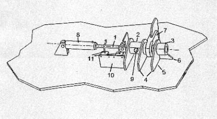
Most important was the Atlantic lock or bottom lock. The arrangement is shown in the sketch below.
This locking device consisted of a locking bolt (1), movable horizontally in a transverse direction, guided in a bolt housing (2). In extended position the tip of the bolt engaged a support bushing (3). The bolt housing was fixed to the forepeak deck by means of two steel lugs (4) and the bushing was installed in a third similar lug (5), to which a support bracket (6) was fitted. A mating lug (7), attached to the visor itself, was located between the bolt housing and the support bushing when the visor was in the closed position and the extended bolt then engaged the hole in the mating lug.
The bolt was moved in the bolt housing between the retracted position and the extended position by means of an hydraulic actuator (8), operated from the control panel located behind the bow and the ramp on the car deck. A spring-loaded mechanical plunger (9), perpendicular to the bolt, engaged grooves in the bolt in the open and closed position, thereby securing the bolt mechanically in its extreme positions, regardless of hydraulic pressure. The bolt was also locked hydraulically at any time because the hydraulic fluid was trapped in the system, regardless of whether the hydraulic system was under pressure or not.
The mating lug at the aft end of the bottom of the visor consisted of a single steel lug, welded to a transverse beam of the visor bottom structure and supported by a bracket. The lug had a hole for the locking bolt with an original diameter of 85 millimetres (see Enclosure 2.6.2.70 - drawing of Atlantic lock).
When the bolt was moving from open to closed position or the other way round, a vertical plate (10), fitted to the bolt initially, contacted 2 mechanical limit switches fitted to the sensor plate (11), which activated the indicator lights on the control panel on the car deck to show "red" when the bolt was open and "green" when the bolt was in closed position. In case the bolt would be in an intermittent position there would be no indicator light shining.
The control panel was located at the forepart of the car deck at port side (see Enclosure 2.6.2.71 - Photo of ESTONIA with the open visor and control panel and Enclosure 2.6.2.72 - Car deck with closed bow ramp). Details of the control panel can be taken from Enclosure 2.6.4.81. The above description as well as the relevant drawing show the condition at the time the vessel was delivered to AB Sally in June 1980.
The Hydraulic Side Locks were installed at about 1/3 of the height of the visor and consisted of two lugs, mounted to the aft bulkheads of the visor and extending, when the visor was closed, into two openings in the front bulkheads of the hull, inside the rubber packings, whereafter hydraulically operated bolts engaged the holes of the visor lugs. The hydraulic bolt installations were similar to that of the Atlantic lock, i.e. a bolt moving in a bolt housing and, when extended, engaging a support bushing. The visor lug inserted between the bolt housing and the support bushing. The bolt was moved by a hydraulic actuator. The position of the bolt, fully retracted and fully extended, was sensed by magnetic type limit switches activating indicator lights.
Additional hydraulic cylinders - so-called ice-cylinders - were installed at each side to push in a forward direction on the visor lugs when the visor was to open. This installation was intended to assist in breaking the visor open in case it had become frozen fast in closed position.
Two vertical stiffeners were installed on the front side of the plating separated by a distance slightly larger than the thickness of the lug itself, to comply with the remark on drawing 49111-330 made by the plan approver of B.V., i.e.
»Local reinforcements of the ship's structure in way of locking devices to surveyor's satisfaction.« (see Subchapter 2.4.3. above).
Directly below these hydraulic side locks, at each side a further set of locking devices, the "manual side locks", were installed consisting of a strong bolt with nut at vessel's side and a strong hook at each side of the visor's aft bulkheads, which also extended through a similar narrow opening into the ship's side. The arrangements of hydraulic and manual side locks can be seen from a respective photo attached as Enclosure 2.6.2.74. The photo shows the hydraulic lock closed, whilst the manual lock is not engaged. In order to demonstrate the dimensions a photo of the mock-up of the manual side lock is attached as Enclosure 2.6.2.75.
After closing of the hydraulic side locks from the control panel on the A-deck the operator or somebody else had to walk into the port side house, up the stairs to B-deck, forward beside the chain locker, then climb through an opening in the deck down into the void space on A-deck from where both the hydraulic and manual side locks were accessible and the bolt of the manual lock could easily be moved between the hooks of the visor. The same procedure had to be repeated at starboard side. The distance to be covered from the control panel to close both port and starboard manual side locks is only about 38 m. The way to walk can be seen from Enclosure 2.6.2.76 (2 pages).
The manual side locks are called "reserve" locking devices in the von Tell manual (Enclosure 2.4.2.31), but B.V. calls them in their letter to the JAIC dated 10.01.95 »2 manually operated fasteners for heavy weather« (Enclosure 2.4.2.37). - See also Subchapter 2.4.2 / 2.4.3.
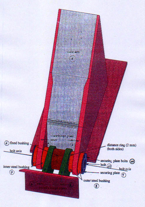
The Visor Hinges
The hinges, around which the visor was opening and closing, consisted of a steel/bronze bushing system fitted through holes in the side plates of the visor arms and two steel lugs with a housing in between welded at both ends of the visor arms to the forecastle deck plating. A stainless steel bolt was leading through each of the assemblies at port and starboard side. Securing plates bolted to the outer respectively inner sides of all four steel bushings prevented moving out of the bolt.
The bearings were lubricated through drillings in the bolt and grease nipples at its ends.
Also the hinge arrangement was von Tell design and the bushings, and subsequently the bolts, were installed under the strict supervision of the von Tell representative Günther Todsen. His statement - attached as Enclosure 2.4.2.21 - shall be quoted in connection with the hinge installation as follows:
Installation of the Hinges
»The bore holes for the bushings were carried out in the shipbuilding hall by means of the a boring machine. I had personally checked and touched the bore holes before the bushings were installed and do confirm that the holes in the visor arms were by no means burnt out. Anyway, I never would have accepted such bungled work as can be on the photos showing the remains of the visor hinge plates of the ESTONIA. In such case that the Yard would not have accepted my objections, I would have the left the vessel and informed my principals.
This happened for example on a vessel at Dunkirk. I was instructed to carry out repairs to some hatch covers. When the crew refused to supply me with the spare parts necessary to perform a proper repair (although these spare parts were on board) and a proper repair, based on my professional experience, would not have been possible otherwise, I refused to carry on working and returned to Kiel.
The steel bushings were welded into the visor arms under my supervision and subsequently milled to such an extent that the bronze bushings did fit. These bore holes were performed very exactly to assure that the port and starboard sides were in exact alignment in order to avoid excessive loads on the hinges during opening and closing of the visor. Thereafter the shafts were inserted, whereby also the distance rings were put in place (2 mm thick). I do remember this work in particular, because it was difficult, time consuming, and required a lot of care. The shafts were made of NIROSTA (stainless) steel and had grease grooves with grease nipples. By means of these grease nipples the hinges had to be greased at least once a week.«Todsen as well as the Meyer Werft managers and employees have time and again confirmed that the bore holes in the visor arms for the steel bushings had been drilled and not burned and, as a matter of fact, the port outer part of the visor hinge plate still shows circumferential drilling marks. The sketch below shows the hinge arrangements in detail.