2.5.3 Propulsion system and control
The propulsion system consisted of four medium-speed diesel engines, connected in pairs to two propeller shafts via gear boxes. The engines were four-stroke turbo-charged engines with eight cylinders and a maximum continuous output of 4 400 kW each. They were designed to operate on heavy fuel oil. Maximum continuous operating revolutions of the engines were 600 rpm which corresponded to 188 rpm of the propellers.
Each propeller shaft carried one controllable-pitch propeller with a diameter of 4.0 m. The port-side propeller rotated clockwise and the starboard side one counter-clockwise.
The pitch control of the propellers was hydraulic, separate for each propeller. The control was effected electrically be power selector levers on the main control console on the bridge, on the bridge wings and in the engine control room. The control signal from the power selector affected the engine revolutions as well as the propeller pitch via an electro-hydraulic "combinator". Revolutions and pitch both increased at increasing power settings up to about 70% output, when the maximum continuous engine revolutions, i.e. 800 rpm were reached. After that, the output could be further increased to 90% by increasing the propeller pitch only while the revolutions of the engines remained at 600 rpm.
All the normal indicators, alarms and control devices were on the bridge and in the engine control room. The installation qualified for unmanned machinery space at sea in accordance with the classification requirements, but actual operation was at all times conducted with the engine control room manned by one engineer and one motorman.
The total fuel oil tank capacity was 940 m³ of heavy fuel oil and 291 m³ of marine diesel oil. Bunkering for a complete round trip was always done in Stockholm.
2.5.4 Electrical system
The three-phase, 380 V, 50 Hz electrical system was fed by four main electrical generator sets. They had an output of 1065 kVA each and were capable of parallel operation. The generators were driven by four diesel engines, each supplying 1104 kW at 750 rpm.
Transformers provided 220 V single-phase power for lighting and utility functions. The main electrical switchboard was in the engine control room.
An emergency generator set in compliance with the SOLAS requirements was installed in a separate room on deck 8 near the engine casing. The generator was powered by a diesel engine with an output of 312 kW at 1500 rpm. It supplied the emergency lighting system and also essential bridge equipment, including engine control, steering system, radars, gyro-compass, logs, echo-sounder, navigation lights, search lights, radio station, telephone system and public address system.
The emergency generator unit was designed to start automatically in case of loss of electrical power in the main network. The total starting and switch-in time was about 15 seconds.
Accumulators for emergency power in case of loss of all other electrical supply were installed in compliance with the SOLAS requirements.
2.5.5 Ballast system
Two centrifugal ballast pumps were installed, each with a capacity of 300 m³/h. The pumps served ballast tanks which were the forepeak tank, the forward trim tank, two double-bottom tanks, one pair of heeling tanks and the aft peak tank, giving a total capacity of 1212 m³.
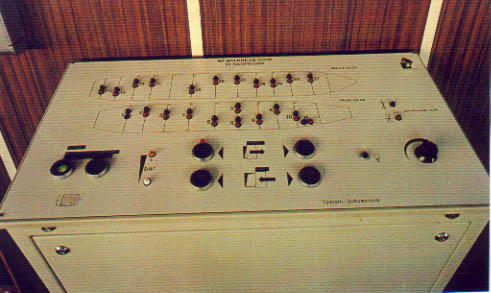
The heeling tanks were side tanks with a capacity of 183 m³ each and intended for adjusting a list of the vessel when needed. The list that could be compensated with one heeling tank full and the other empty was about eight degrees. A separate heeling tank pump could be operated from the deck office at the stern ramp and from the engine control room. The connection valve between the heeling tanks (cross-flooding valve) was designed to close in case of failure of electrical power. The open/close condition of this valve was indicated by red/green lights on the control panel for the watertight doors on the bridge. - See photo below.
Picture of control panel of WT bulkhead doors
2.5.6 Car deck arrangement
The vessel had a deck for loading trucks, cars and other wheeled cargo. The car deck was the vessel's freeboard deck and identified as deck number 2. It extended from side to side and from bow to stern, with a centre casing immediately starboard of the centre line. The available deck space was divided into four lanes on the port side and three on the starboard side. Lashing fittings were mounted along the lanes on the car deck.
Personnel access to the car deck was via stairs and lifts in the centre casing. Four of the lifts had doors leading to the starboard side of the car deck and one had doors to the port side. A total of eleven doors, six starboard and five port, led from the car deck to the stairs inside the casing. The doors were sliding-type steel doors, meeting the SOLAS fire resistance requirements. The locks of the doors were remotely operated from the Information desk on deck 5. The doors were not locked at sea.
The car deck space was ventilated by electrically driven fans, located on both sides at the forward and aft ends of the deck area. The air channels ended at the open deck 4, on the forecastle deck level in the front bulkhead of the superstructure.
Twelve closable 4" scuppers were installed along each side of the deck. The scuppers were normally left open.
Four TV cameras for monitoring the car deck area were mounted.
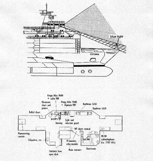
2.5.7 Bridge layout
The navigation bridge was on the uppermost deck (deck 9), 9.2 m aft of the forward end of the superstructure. The bridge wings extended over the ship's sides by about 1.5 m and were fully enclosed.
The central part of the bridge extended forward of the wings by about 2 m. In the original design there was a console containing all major navigation and control equipment at the front bulkhead, just below the windows. The steering console was located on the centre line, just behind the front windows. The bridge was rebuilt in January 1994 and some of the navigation equipment was renewed. The navigation console at the front bulkhead was partly removed, and a new conning station was installed to port of the centre-line. The design of the conning station was of the Pilot-Copilot type, commonly used in Baltic ferries.
The new console contained two ARPA radars, DGP's (Differential Global Positioning System) receivers, the main auto-pilot, propulsion control levers, VHF telephones, mobile telephones and equipment for internal communications. From the two navigators' seats, and the captain's seat, normally placed to the port of the conning console, the panel with indicator lamps for visor and ramp was within sight.
The fin stabilisers and associated controls were also installed in 1994. The original "Roll-Nix" stabilisation system had been found inadequate. It was, however, not removed and had sometimes been used in strong following wind.
A separate chartroom was located on the starboard side, in the aft part of the bridge. The corresponding space on the port side was an open area containing the fire alarm centre and various cabinets for storage, etc.
The main entrance to the bridge, from the accommodation, was on the centre line at the aft end of the bridge, where a door to the staircase connected the bridge with the officer and crew accommodation on decks 8 and 7. On the port side at the aft end of the bridge there was a door to the open deck.
Because of the retracted position of the navigation bridge, only the flag pole on the bow of the vessel was visible from the conning station - see drawing below - whilst the most forward part of the visor could be seen through the two windows on deck level at both sides of the extended central part of the bridge, as can be seen on the drawing below. A monitor, showing among other things, the transmissions from the four car-deck cameras, was placed at the chartroom entrance and could not be seen from the conning station.
2.5.8 Navigation equipment and systems
The navigation equipment was of a high standard, and met the requirements for the intended trade.
The equipment had been upgraded and/or renewed on several occasions, and at the time of the accident the following equipment was installed on the bridge for navigation and vessel control:
* Radar, Atlas 9600 Arpa X-band - 3 cm
* Radar, Atlas 8600 Arpa S-band - 10 cm
* Radar, Raytheon 1650 12 SR Raycas
* Radar, Raytheon 1650 SR (slave to Radar set 1650 12 SR Raycas)
* 2 Gyro compasses, Sperry MK 36
* Magnetic compass, Plath
* Autopilot, Kockum Steermaster 2000
* Autopilot, Sperry Universal
* Speed Log, Raytheon Doppler Sonar (one axis)
* Echo-sounder, Simrad DSN 450
* Radio direction finder, Debeg ADF 7410
* Antiroll system, Roll Nix (SSPA)
* Stabilisers, Brown Brothers folding fins
* Navigation computer, Navi Master NM-100
* GPS receiver, Shipmate 5800 C
* DGPS receiver, Shipmate 5360
* DGPS receiver, Magnavox 200
* Speed/Fuel Consumption Optimisation Computer, ETA Pilot
2.5.9 Communication equipment
The communication equipment was divided between the bridge and the radio room.
The vessel's radio room was on deck 8, aft of the captain's cabin. The radio room was mainly used for commercial communication, and contained the following equipment:
* Main Transmitter, Standard Radio ST-1680 A
* Main Receiver, Skanti AS SR-51
* Emergency Transmitter, Standard Radio ST-86 B, A1, A2, A3
* Emergency Receiver, RL Drake RR-11
* Autoalarm IMR A4 734/SRT B-2290 1000
* VHF Svensk Radio STR-40 - ME62 In addition to the equipment in the radio room, the following was installed on the bridge:
* MF/HF radio telephone
* VHF Svensk Radio STR-40 ME62
* VHF Sailor (1 master and 3 slaves)
* VHF Skanti
* Watch Receiver DC-300D
* NAVTEX receiver
* Lifeboat Radio IMR SOLAS III A
* Mobile Telephone NMT 450
* Weather Fax Receiver Two Emergency Position-Indicating Radio Beacons (EPIRB) were mounted, one at each side on top of the bridge.
![]()