![]()
2.4.6
The construction phase
In this subchapter only the construction respectively installation of those components shall be described which have actually played a role in the sequence of events having led to the sinking of the ESTONIA respectively which are considered to be of relevance by the JAIC. These are:
(a) Bow visor:
- hinges
- lifting cylinders
- locking devices
- rubber packings(b) Bow ramp:
- locking devices
- hingesThe respective yard drawings are:
- 1101a: Foreship frame 149 forward to A-deck
- 1103 : Bow visor
- 1104 : A-deck to C-deck frames 138 - 160
- 1106 : Interlock of bow visor
- 1107 : Roofs for bow visor hinges
- 1108 : Bolts for bow visor hinges
- 1109 : Bushings for bow visor hinges
- 1109a: Bushings for bow visor hingesvon Tell drawings:
1. 49111-301a : Bow ramp
2. 49111-302 : Details for bow ramp
3. 49111-303 : Details for bow ramp
4. 49111-305 : Outer hinges of bow ramp
5. 49111-330 : Bow visor/ bow ramp general arrangement
6. 49111-360 : Arrangement of hydraulic locking devices of bow ramp
7. 49111-361 : Locking devices for bow ramp
8. 49111-371 : Locking devices for bow visor
9. 49111-372 : Arrangement of hydraulic and manual locking devices of visor
10. 49111-373 : Atlantic Lock
11. 49111-387 : Layout of pipes and hoses for actuators of visor and bow ramp
12. 49111-391 : Location of actuators for visor
13. 49111-801 : Hydraulic scheme for drive-on ramps, hanging decks, visor, bow ramp, stern ramps
14. 49111-804 : Pump station with connection scheme, stern aggregate
15. 49111-805 : Pump station w. connection scheme, forward aggregate
16. 49111-825 : Control panel for visor and bow ramp
17. 49111-871 : Location of sensors and limit switchesIn addition to these "working drawings" there were numerous detail drawings which were required for production and control. The reference numbers can be found in the box at the upper right side of each drawing. Some of these detail drawings can also be found in the "Drawing file" behind the respective master drawing. In the "Drawing file", which is part of this documentation, all the above listed drawings as well as the General Arrangement Plan are compiled.
In detail:
(a) - The Bow Visor was built in the fabrication hall according to drawings of Messrs. von Tell AB, Gothenburg in the same way as already one year before the visor for DIANA II had been built. It was moved out of the hall into the open on 15.01.80 and remained there until it was fitted to the vessel between 01.03. and 15.3.80.
During the time the visor was in the open air storage the hinge plates to be fitted to the visor arms and at the forecastle deck were fabricated and the following line of production developed:
- 1:10 shop:
Based on the original drawings, 1:10 scaled "burning sketches" were made and fed into the photo electric scanner steering the cutting machine, which subsequently cut out lugs for Atlantic lock, hinge plates and side locks, which thereafter were transported to the locksmith shop. Atlantic lock lugs were 15 mm respectively 60 mm in diameter, side locks and hinge plates were 60 mm thick. All parts subsequently to be welded to vessel's structure were oversized in length. The colour of the basic primer was yellow as can be seen from the photos attached as Enclosure 2.4.6.63.
- Locksmith shop:
Holes with diameters according to drawings supplied were drilled into lugs and hinge plates whereafter the parts were transported to the visor. - Welding of hinge plates: The hinge plates were welded to the visor. During the welding procedure its proper alignment was assured by the use of a pipe prepared specifically for this purpose having the exact diameter of the hinge plate bores. One photo shows the visor in open air with hinge plates already fitted (Enclosure 2.4.6.64).
- Transport of visor alongside vessel.
- Positioning of visor on the vessel, connection established by welding several steel bars between visor/vessel's hull as can be seen on the photo attached as Enclosure 2.4.6.65. Please note the basic yellow primer.
- Hinge system made fit for functioning by cutting the hinge plates for vessel's side to the required length, welding hinge plates to forecastle deck after proper alignment had been ascertained by the use of the above-mentioned pipe tool. Welding of steel bushings into the bores of the visor's hinge plates always assuring proper alignment by means of the pipe tool, finally shrinking the bronze bushings into the steel bushings, fitting in the Nirosta bolts and fixing the securing plates. The visor hinge system is explained by the drawing attached as Enclosure 2.4.6.66.
The von Tell representative G.Todsen had supervised and controlled the Yard's work with parts delivered by von Tell and with parts fabricated by the Yard according to von Tell drawings. He also assisted whenever required. This refers in particular to the installation of safety relevant parts, such as the hinges, the locking devices, the lifting cylinders, and rubber packings. In detail the activities of G.Todsen have been explained in his statement attached as Enclosure 2.4.2.21.The installation of the visor hinges have been carried out - according to Todsen - as follows:
»Installation of Hinges The bore holes for the bushings were made by means of a boring mill in the fabrication hall. I personally took a close look at the bore holes and touched them with my fingers before the bushings were installed and can confirm that by no means were they burned holes. I would never have accepted such dubbed work as can be seen on the photographs shown to me of the remnants of ESTONIA's hinge plate. In case the yard would not have taken notice of my objections, I would have left the ship and would have informed my principals accordingly.
Under my supervision on board the steel bushings were welded into the visor's arms and subsequently bored out to the extent that the bronze bushings did fit. These bores were carried out with extreme precision in order that port side and starboard side were in alignment in order to avoid breaking tension when opening resp. closing of the visor. Subsequently the bolts were guided in whilst simultaneously the distance rings (2 mm thickness) were fitted. I recall this work especially because it was rather fumbly work. The bolts were made of Nirosta steel and had a grease groove with grease nipple. By means of theses grease nipples the hinges had to be greased at least once a week by grease gun.«(b) The Lifting Cylinders (actuators) were also supplied by von Tell and installed under the supervision and upon instructions of G.Todsen. Thereby the same care was applied as had been done with the installation of the hinges.
(c) The Atlantic Lock was also of von Tell design and mainly also supply. The Yard fabricated only the 3 steel lugs at vessel's side plus the visor lug and carried out the installation under the supervision of the von Tell representative G.Todsen. The von Tell supply can be taken in detail from drawing 49111-373 - Atlantic Lock - to be found in the "Drawing file". The yard performed as follows:
The lugs of the Atlantic lock were cut out according to the respective burning sketches in the 1:10 shop. The thickness of the 3 lugs to be welded to the forepeak deck were 15 mm each and the visor lug was 60 mm. The parts subsequently to be welded to vessel's structure were oversized. Thereafter the lugs were transported to the locksmith shop, where the holes were drilled into the lugs according to the relevant drawings and were subsequently transported to the welders shop. Here one support bushing was welded into the starboard lug, whilst the centre and port lugs were connected by another bushing, called "bolt housing" by the JAIC, which was welded into the holes of both lugs.
Both bushings were welded into the lugs by means of 7-8 mm seams from both sides in accordance with yard standard and according to the von Tell drawings whilst the lugs were lying flat. Performance was closely supervised by the von Tell representative G.Todsen, who specifically stated that he never would have accepted the 3 mm welds visible on the pictures showing the remains of the Atlantic lugs. In this connection G.Todsen explains (see his Statement - Enclosure 2.4.2.21):»The three lugs, welded to the A-deck, as well as the lug at the aft part of the visor's bottom are yard-supply. The 3 first mentioned lugs had been constructed with overmeasure. It can be seen from the respective drawing that both bushings, the bolt, the cylinder including piston rod, and the limit switches (sensors) had been delivered by von Tell. The lug of the visor was welded and used as fixing point for the alignment of the other three lugs of the Atlantic lock.
At the workshop both bushings had been welded into the lugs in such a way that the large bushing fitted between the middle and the port lug and the small bushing into the starboard lug with the support bracket. As already mentioned above, I have had detail drawings for all components from which among others also the thickness of the welding seams were revealed.
The installation of the Atlantic lock was carried out as follows when the visor was closed:
- The fixing point was the lug of the visor,
- accordingly hydraulic cylinder and the 3 lugs with already previously welded bushings were aligned, burned to fit and welded.
Thereby I paid special attention to the even welding of the 3 lugs to the A-deck, i.e. inner and outer side the same. Furthermore, I took care that below each lug, in the void space under A-deck, a reinforcement was fitted.«(d) The Side Locks were of similar design and construction as the Atlantic Lock, with all components supplied by von Tell and the Yard only fabricating the steel parts and performing the installation under the supervision of von Tell. This was carried out as follows:
The visor was closed and the required length of the lugs measured, the lugs cut respectively. Location of lugs was marked at both bulkheads, the visor partly opened, and the lugs welded on to the bulkheads. Thereafter the cleats of the manual locks were also welded to the bulkheads. Flat bars welded at the inner side of the bulkheads according to class surveyor's requirements and under supervision and control of the von Tell representative G.Todsen.(e) The Rubber Packings were installed on the forepeak deck to assure weathertightness of the visor and a firm and tight connection between visor and vessel once the locking devices were closed. By this tight connection high frequency vibration of the visor with respective effects on its fixing points were avoided. In this connection G.Todsen explains:
»Prior to installing the 50 mm thick rubber gaskets every 300 - 400 mm the distance between the opposite parts visor/ship were measured by means of an inside calliper and the deviations ascertained were compensated by flat iron. This way guaranteed that the rubber gaskets installed afterwards had absolutely the same contact pressure, as the visor was pressed into the rubber gaskets up to 8-10 mm, which made the inside of the visor watertight (weathertight).
During the trial trip to Helgoland, among other things also the visor was checked in respect of its tightness. The visor was totally locked, i.e. also the manual locking devices were closed.
During full speed - i.e. about 2,5 m high bow wave and slightly pitching vessel - myself, Mr. Lohmann, surveyor of Bureau Veritas, and a representative of the owners, whose name I do not remember, were inside the visor and noted that the visor was not totally watertight, but at some places water was slightly leaking through. After returning to Emden the rubber packings were marked with chalk, the visor was closed and opened again. Due to the remaining imprints the leakings were found out and the rubber packings were raised in these particular areas. During a subsequent tightness test the visor was found to be tight and finally accepted by the owners, the Classification Society and the Finnish Board of Navigation.
The official delivery took place already on 20 June 1980 - after successful function test on 19 June 1980. Afterwards the attached Delivery Certificate was filled in and signed by representatives of the owners, the B.V., the shipyard and my colleague Brandt.«B.V. surveyor Lohmann also remembers that during trials some minor leakage was noted. He also remembers that after return to Emden the respective rubber packings were adjusted and a subsequent test revealed the visor to be watertight i.e. weathertight in SOLAS terminology.
(f) The Bow Ramp was also installed under the control and supervision and with the assistance of G.Todsen. His comments are:
»The bow ramp as well had been installed and arranged under my supervision. The securing bolts were made to fit. During locking of the ramp at first each one hook on each side of the corresponding parts of the ramp lowered and pulled the ramp inwards, up until a special point had been reached and passed. Now the ramp was tight in position. Then two bolts on each side moved out of the ship into the corresponding pockets of the ramp.
The bolts snapped audibly into their end positions. As from the control console on the car deck neither visor nor ramp locking devices could be seen, the operator had to rely on the control lamps and his sense of hearing. It was clearly audible by the snapping noises when the bolts engaged the pockets. Only after the bolts had fully engaged did the sensors become activated, which - if all bolts and also the hooks were in contact with the sensors - led to the "green light" at the control console as well as on the bridge, i.e. the ramp was closed and locked.«The complete statement of Günther Todsen is attached as Enclosure 2.4.2.21.
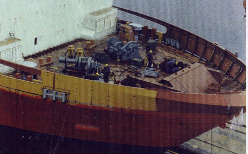
The picture below shows the foreship during the construction phase.
![]()